
How AI Is Transforming Daily Work in Service Teams
Reduce downtime and improve service efficiency with AI-powered troubleshooting. Learn how service teams use ilean to solve problems faster and capture knowledge.
Corridors can be used in Civil 3D to design linear elements like roads, railway lines or retaining walls.

The assembly will be extruded along the baseline of the corridor to generate the object, which is what is required in most situations. However, sometimes we can have discrete elements in the assembly that need to be inserted at a certain interval along the baseline, rather than added as a constant extrusion. This is what happens with railway sleepers, also known as railroad ties or crossties.
A possible approach can be to use a conditional subassembly and apply a different assembly to the corridor based on the presence or absence of a polyline along the baseline of the corridor. In this example, we will be using Dynamo to automate the creation of those polylines, that will then be applied to the corridor as a target of the conditional subassembly.
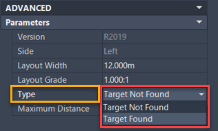
To create the assembly, we start by inserting the ‘ConditionalHorizontalTarget’ subassembly directly in the baseline of the assembly. It needs to be inserted twice, once with the ‘Type’ parameter set to ‘Target Not Found’ and again with ‘Target Found’.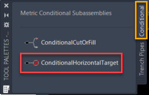
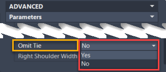
To illustrate this workflow, we will use the ‘Internal_Multi_Track’ subassembly. Omit the tie when the target is not found and include it when it is found.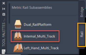
The resulting assembly is shown below. Note how the railroad tie only displays when the target is found.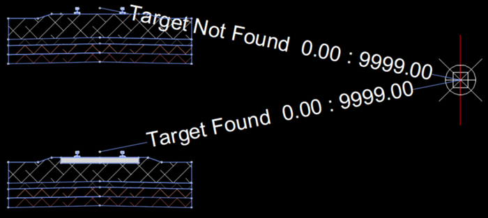
Our next task is to draw some polylines along the baseline of the corridor where the sleepers should go. The following steps will guide you through the creation of a Dynamo script to achieve this goal.
Select the corresponding baseline from the corridor.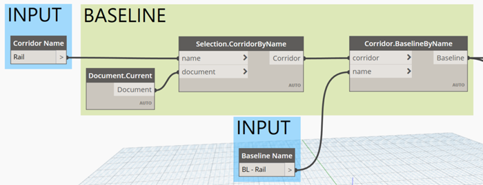
Using this baseline, the following group will generate a list with the start and end chainages for all the polylines. The width and spacing of the tie are provided as an input and the resulting chainages will be centred around the baseline ensuring that no ties go beyond the start or the end chainages of the baseline.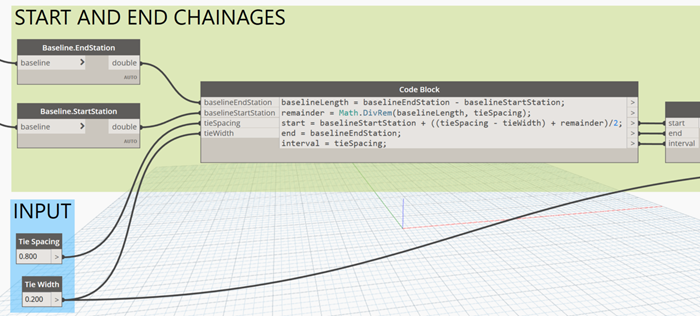
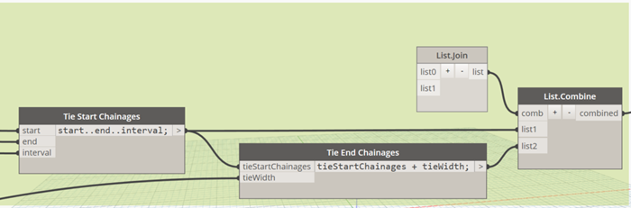
Extract the start and end points of the polylines from the baseline using the list of chainages that we calculated previously. Those points will then be used to insert the polylines in the drawing in a layer of our choosing.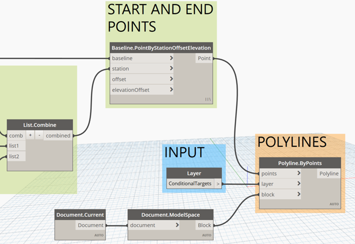
To finish the script, we check the ‘Is Input’ property for all the input nodes to enable the script to be executed from Dynamo Player.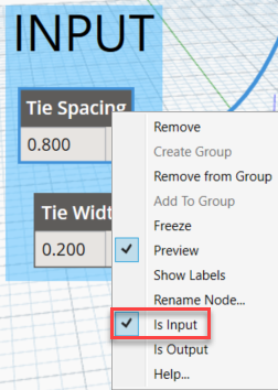
Execute the Dynamo script adjusting the inputs accordingly.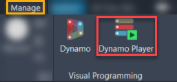
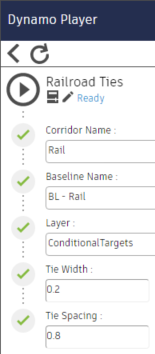
After executing the script, you will see some polylines along the specified baseline with a length equal to the ‘Tie Width’ and a distance between them based on the ‘Tie Spacing’ provided. These polylines indicate where the sleepers should be placed.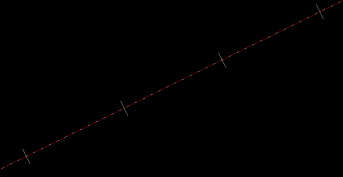
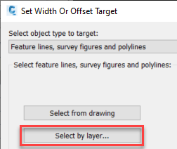
There just remains to apply those polylines as targets of the conditional subassemblies in the corridor. Since all of those polylines have been created in the same layer, all of them can be easily selected at once.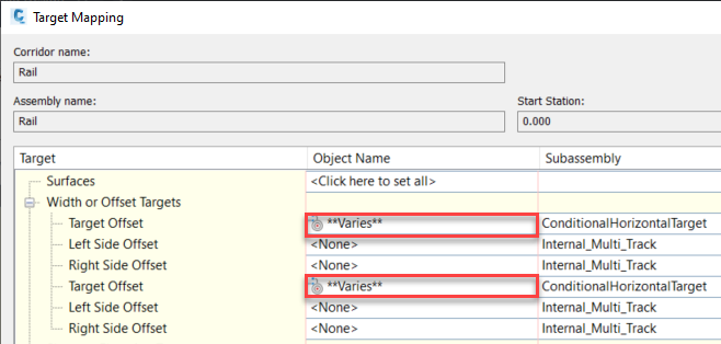
The resulting corridor can be seen below, with the sleepers shown in red. The ballast reaches the top level of the sleeper in the gaps between them.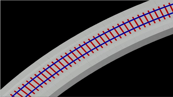
If you would like to improve your Civil 3D and Dynamo skills, you can have a look at our courses here.
Alternatively, our Civil Engineering consultancy services can be found here.
Reduce downtime and improve service efficiency with AI-powered troubleshooting. Learn how service teams use ilean to solve problems faster and capture knowledge.

As organisations continue to adopt AI, expand their cloud estates, and support more flexible ways of working, the security landscape is becoming more complex. The challenge in 2026 isn’t just preventing attacks, it’s maintaining visibility, protecting data in new workflows, and ensuring the business can recover quickly when disruption occurs.
The construction industry is entering a new era, and Bluebeam is once again leading the way. In 2026, Bluebeam Max will launch as a new premium subscription that combines the power of Revu with advanced AI technology. This blog highlights just some of features you will expect to see within Bluebeam Max.