
How AI Is Transforming Daily Work in Service Teams
Reduce downtime and improve service efficiency with AI-powered troubleshooting. Learn how service teams use ilean to solve problems faster and capture knowledge.
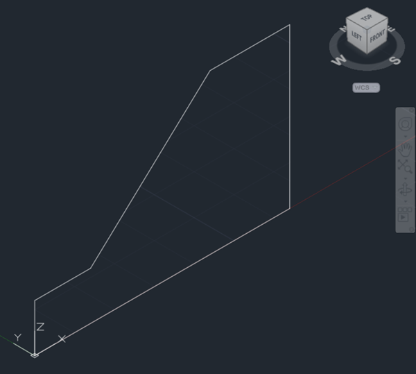
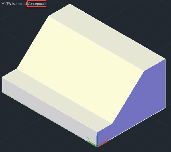
AutoCAD is widely known and utilised as a 2D drafting tool. However, its use for 3D modelling is not as prevalent. This post introduces AutoCAD users to some of the most common 3D tools in AutoCAD by creating the simple shape shown below.

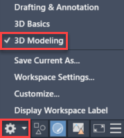
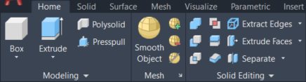
Before we start modelling, we need to change the workspace to “3D modeling” from the status bar at the bottom of the application. The ribbon will update to show 3D tools.
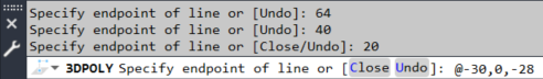
You can start by navigating to an isometric view by clicking on a corner of the view cube on the top right of model space. If you do not see the view cube, you can make it visible from the ‘View’ tab of the ribbon. Launch the 3DPOLY command to draw a closed 3D polyline in the front view (XZ plane). Starting on the origin and with ortho mode on (F8), start drawing as you would in a 2D view, keeping in mind that if you specify coordinates, you will need to provide them in all three axes.
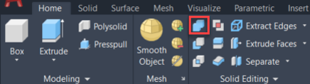
Select the EXTRUDE command from the ‘Home’ tab of the AutoCAD ribbon, pick the 3D polyline from the previous step and then type 90 as the height of extrusion to create a 3D solid. You can control the visual style from the top left corner of model space.
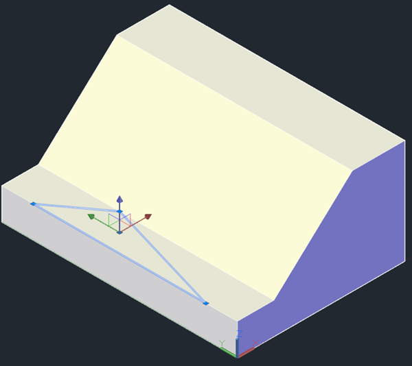
Draw a triangle using a closed 3D polyline as shown below and extrude it to the back of the shape. You may find the ‘Extension’ object snap useful to find the vertices of the triangle.
At this point, we have two independent solids that intersect. Pick the UNION command and then select them both to combine them into a single object.
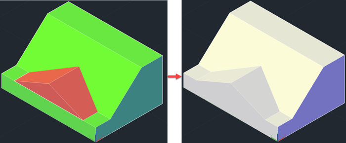
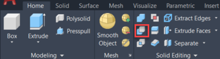
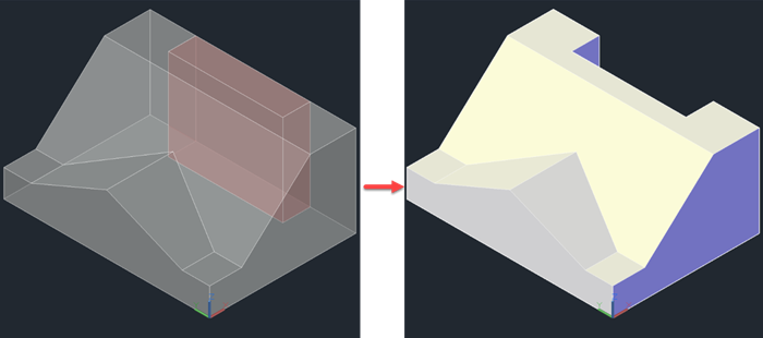
To finish the shape, draw a rectangle on the top face and extrude it to the base. Using the SUBTRACT tool, select the solid to subtract from first, press <Enter>, and then select the solid to subtract.
I hope you found this quick introduction to the 3D tools in AutoCAD useful. If you would like to learn more about this topic, you may want to consider our AutoCAD 3D Drawing and Modelling training course.
Please submit your enquiry here and a member of our team will get in touch.
Alternatively call 0345 370 1444
Reduce downtime and improve service efficiency with AI-powered troubleshooting. Learn how service teams use ilean to solve problems faster and capture knowledge.

Cybersecurity risks are not always caused by sophisticated attacks or major system failures. In many cases, risk builds quietly through everyday habits, overlooked processes, and limited visibility into where data is stored or how users interact with systems.

Learn how to reduce cyber risk through stronger security foundations. This month's bulletin covers home office security, legacy technology risks, vulnerability management, MFA, and cybersecurity best practices.