
How AI Is Transforming Daily Work in Service Teams
Reduce downtime and improve service efficiency with AI-powered troubleshooting. Learn how service teams use ilean to solve problems faster and capture knowledge.
In this blog, we will explore how to force slope arrows to point downhill using Autodesk Civil 3D.

When we label a surface with slope arrows in Autodesk Civil 3D (by clicking in the Ribbon -> Annotate Tab -> Labels & Tables panel -> Add Labels dropdown -> Surface -> Slope) we are offered two options (One-point or Two-point):
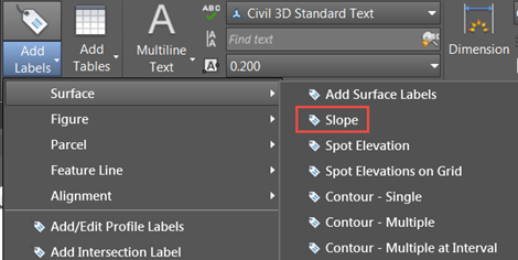
![]()
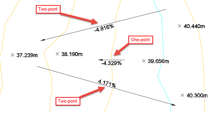
If you choose one point, the slope label will be always pointing downhill in the direction of maximum slope. However, if you select the two-point option the arrow will point from the first point you click to the second. If the level increases in the direction of the arrow (the arrow points uphill) the value of the slope will be positive. If the arrow points downhill, the value will be negative.
If you have ever taken an Autodesk course on Civil 3D, you are probably familiar with this already. We would like the value to be positive and to indicate the direction of the slope with the arrow, which should always point downhill. Additionally, three decimal places are rarely necessary. One decimal place gives us enough information in most cases. In the following steps, we are going to create a style for the slope label to be displayed in this way.
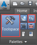
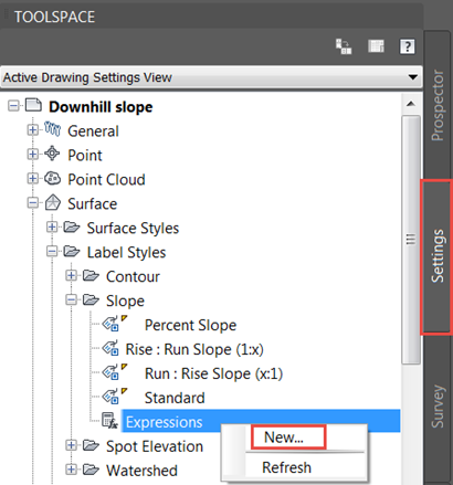
In order to change the direction of the arrow automatically, we need to create a new expression first. Make sure that Toolspace and the Settings tab are showing by selecting them on the Ribbon -> Home tab -> Palettes panel, as shown below. Then, on Toolspace -> Settings tab, Expand Surface -> Label Styles ->. Slope, right click on Expressions and click on New.
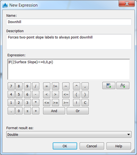
In the window that pops up, give a name to the new expression (we will call it Downhill in our case), optionally add a description, type in the expression IF({Surface Slope} <= 0, 0, pi) and click OK.
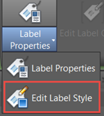
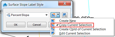
Select all the slope labels in the drawing and, on the contextual Ribbon that appears, expand Label Properties and click on Edit Label Style. On the next window, create a copy of the Percent Slope style as shown below.
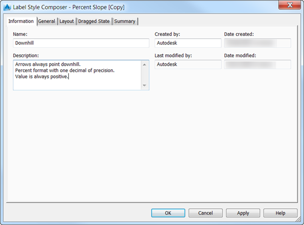
In the information tab, give the newly created style a name and optionally a description:
Go to the Layout tab and select Slope Text under Component name. When you click on Contents under Text, three dots will appear on that cell. Click on them to continue to the next step.
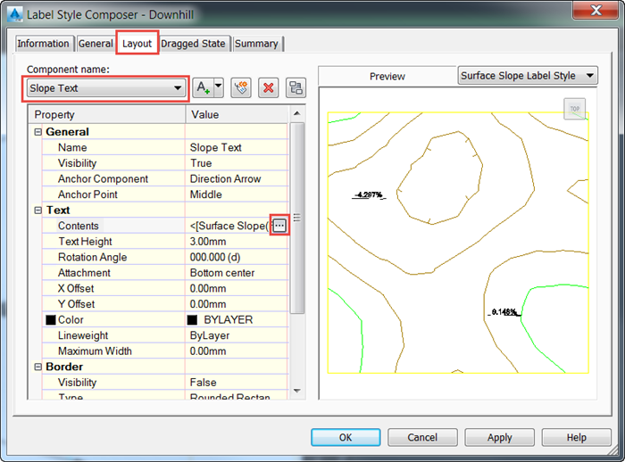
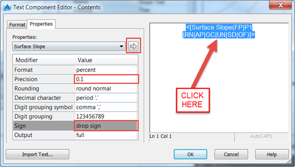
Firstly, highlight the text on the right by clicking on it. Change the precision to one decimal place and drop the sign to show the value as always positive, as indicated in the screenshot. Please note that you must click on the arrow which points to the right for the changes to take effect. Once you have done that, click OK.
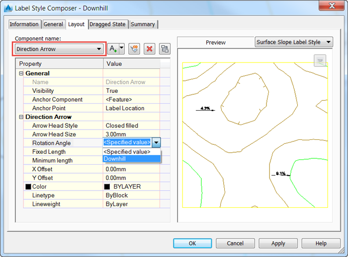
You will get back to the Label Style Composer window. Select Direction Arrow under Component name and click on the dropdown to the right of Rotation Angle. The expression that we created earlier will be available for us to choose. We can select it and click OK. Then click OK again to apply the new style to all your labels, which you had previously selected.
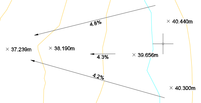
If we have a look at the expression again [IF{Surface Slope}<=0,0,pi)], we can see that it will rotate the arrow pi radians when the surface slope is positive (that is, the arrow points uphill) and leave it unchanged (rotate it 0 radians) when it is already pointing downwards, effectively ending up pointing downhill in any case as we intended. Note: this is only necessary with two-point slope arrows, as one-point arrows always point downwards by default.
The slope labels in our example now display like this:
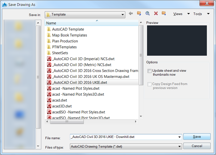
As the last step, if you wish you can save the drawing as a template so that the style that has been created is available for us to choose in future drawings:
If you would like to brush up on your Civil 3D skills and make the most of its tools, explore our Essentials course or take a look at the whole range of Civil 3D courses that we offer at SYMETRI.
Reduce downtime and improve service efficiency with AI-powered troubleshooting. Learn how service teams use ilean to solve problems faster and capture knowledge.

Cybersecurity risks are not always caused by sophisticated attacks or major system failures. In many cases, risk builds quietly through everyday habits, overlooked processes, and limited visibility into where data is stored or how users interact with systems.

Learn how to reduce cyber risk through stronger security foundations. This month's bulletin covers home office security, legacy technology risks, vulnerability management, MFA, and cybersecurity best practices.