
What are Autodesk Inventor Representations?
Representations can be used to maintain a group of saved states or attributes for an assembly document. This could include things like camera angle, constraint value, component visibility, appearance and component suppression.
These attributes typically fall into 3 categories:
- View
- Position
- Memory and Detail management
For this reason, Autodesk Inventor offers 3 different representations:
- View Representations
- Positional Representations
- Level of Detail Representations
These representations can be used individually or in combination.
What does each Inventor Representation type have to offer?
The following table offers a description of the usage and areas of impact for the different representation types.
| |
View
|
Position
|
Level of Detail
|
|
Purpose
|
Control component visibility enabled state, appearance overrides, camera position, parts list filters and work feature visibility
|
Display assemblies in different physical positions or states
|
Control visibility and manage memory consumption by suppressing components or by substituting a single part to represent the assembly
|
|
Used to manage
|
Visibility along with other attributes listed above
|
Constraint value, grounding status, positional offset values
|
Component suppression (load/unload from memory), assembly simplification (substitutes)
|
|
Browser representation
|
Greyed out (unavailable)
|
Bold text
|
Strikethrough for suppressed components, not shown in a substitute
|
|
Effect on graphics window
|
Visible/not visible Enabled/Not enabled (opaque/transparent)
|
Modifies position of assembly components
|
Suppressed components are not displayed (bounding box visible on mouseover) Single part displayed if in substitute rep
|
|
Effect on assembly BOM and drawing manager parts list
|
Yes - parts list can be filtered to show only design view members
|
No
|
No
|
|
Affects system memory consumption
|
Yes*
|
No
|
Yes - removes suppressed components from memory
|
|
Drawing manager command access
|
Base View, Edit View
|
Base View, Edit View (for Base View only)
|
Base View, Edit View (for Base View only)
|
|
Usage in drawing manager
|
Creating custom or speciality views without reorganising the assembly (include/exclude) Speed up view generation, filter the parts list to show only design view members
|
Showing assemblies in different positions
|
Suppressing detail, such as internal parts and/or standard components or simplifying the model to speed up view generation
|
*View representations can lower graphics memory consumption and speed up view creation due to hidden lines not being calculated for invisible components. They can also affect system memory, if an assembly is loaded using a View representation, not all portions of the invisible file/s are loaded into memory. However, if all components are turned on, all segments are loaded into memory. Once loaded, turning visibility off does not unload any part of the file from memory. Use suppress in Level of Detail representations to better manage memory consumption.
How to Create Representations?
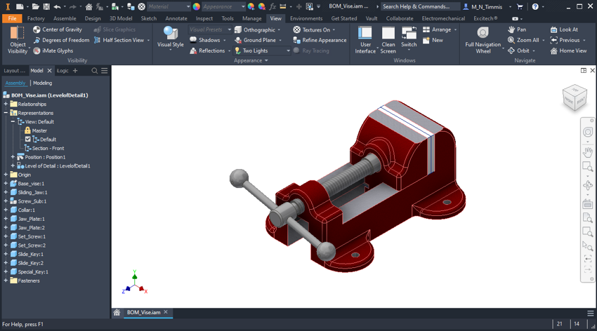
Within the Autodesk Inventor Assembly template by default there are several default representations already in place, as highlighted below:
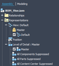
Generally, I tend to recommend leaving these default representations alone, as there are elements of Inventor which use these and look for them. Therefore, if you want to use Representations, then I would suggest creating your own ones to organise and manage the options you want.
When it comes to creating your own Representations, the method is the same for each of the three types. To add a New Representation simply right click the top branch from the type of Representation you are trying to create.
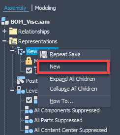
This will then create a new Representation, the name will be View1, Position1 or LevelofDetail1 respectively.
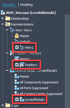
It can be helpful to rename these to represent the contents of the Representation that you wish to store. For example, a View Representation storing a half section could be “Section – Front”. Or a Position Representation storing an open position could be “Position – Open”.
Once you have your new Representation and a relevant name assigned, you can carry out the tasks required to generate the information you wish to store in the Representation. Below are just a few examples for each of the three Representation types, but hopefully gives you an idea of how and what can be achieved.
View Representation:
For this first example, I am creating a View Representation to capture information for a half section view, which can be useful if you find yourself putting a section on and turning it off continuously. This way you only create once in a View Representation, then switch between this and the Default View Representation. In addition to applying a half-section, the view has been changed to look at the file in line with the section and zoomed in to fit.
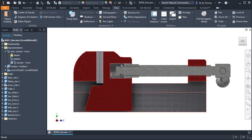
Once you are happy that you have done everything you need in the active View Representation, it can be advantageous to hit Save, to ensure all your data is captured. To then remove the section, or go back to the original view, simply double click on the Default View Representation to activate. This will load the contents of the Default View Representation, which does not include a half section and has a different camera position and zoom factor.
I will run through one more example, this time assigning a colour override. Be aware that when you create a new Representation, it is based upon the current active one. Therefore, because I do not want a colour Representation with a section, I have made sure the Default Representation is the active one.
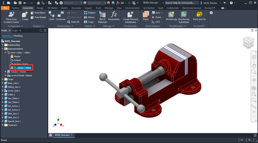
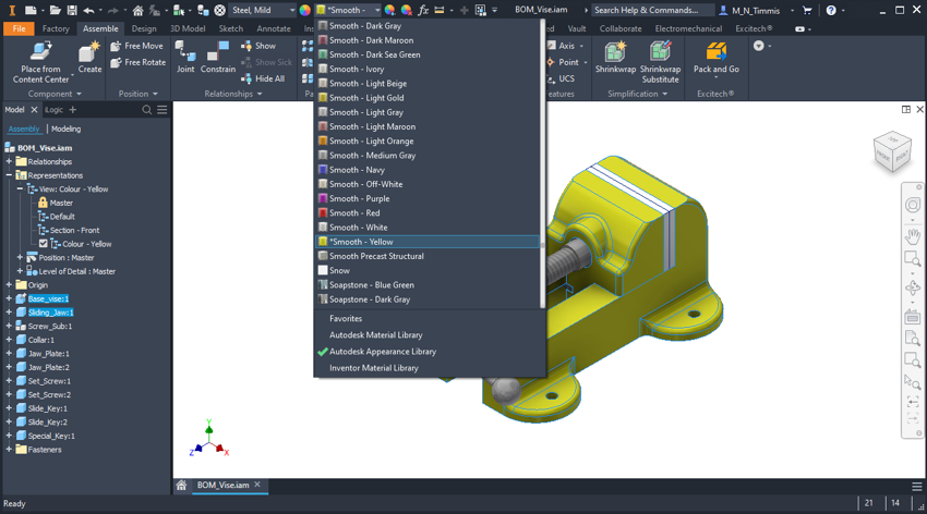
To override the colour, simply select the components you want to adjust. Then select the relevant Appearance from the drop-down.
Position Representation:
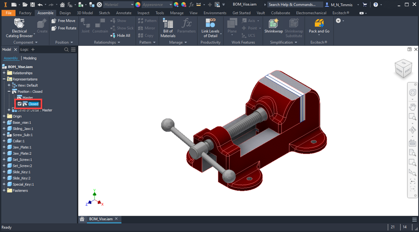
These types of Representations are extremely useful where you have movement in your design, and you want to store information about the extremes of movement or check clearances or lock a position for your drawing views for example. Here we will create two Position Representations, to capture the clamp in Open and Closed positions.
As soon as a new Position Representation is created, Position1 is added to the list, due to the clamp already being in a Closed position. I will just rename this to Closed.
Following this another new Position Representation is added, this time renaming to Open.

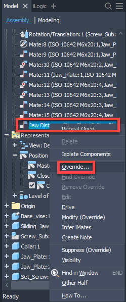
To change the position of the clamp, so that it represents an open position. The constraint currently holding the clamp closed needs to be overridden. Therefore, the relevant constraint is tracked down in the Relationships folder, then a right-click shows an option to Override.
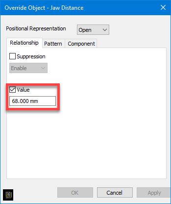
Once the Override Object dialogue is open, the Value option can be ticked, and the required distance entered to Open the clamp to the required position. Click OK to continue, at which point the component/s will move to the relevant position and you will find that the constraint is highlighted in BOLD, to let you know that the constraint has an Override in the active Position Representation.
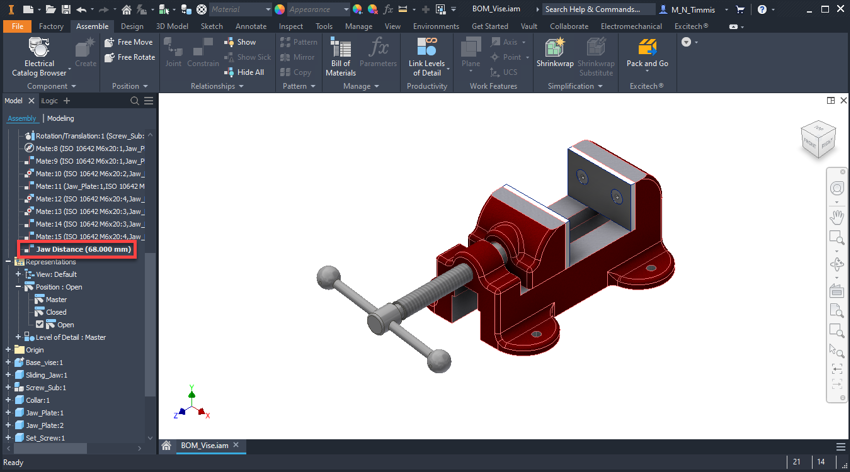
Now you can switch between the Position Representations by double-clicking on the required option.
Level of Detail (LOD) Representation:
Level of Detail Representations can be used for several applications, but typically these are aimed at saving memory in Assemblies. This is due to the nature of suppressing components, which offloads the model data from the current session of Inventor. Therefore, turning off various components and their model complexity can lead to less system memory usage.
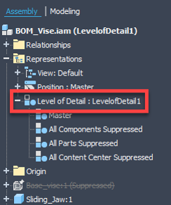
Within the default Assembly template, you will find four pre-existing Level of Detail Representations:
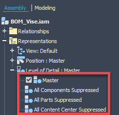
The Master Level of Detail is generally the default one and must have all components un-suppressed within it. Therefore, if you try to suppress a component with Master active, then Inventor will create a temporary Level of Detail to store the Assembly with a component suppressed. This is highlighted at the top of the branch with “Level of Detail: LevelofDetail1”.
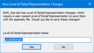
If at this point you try to save the Assembly, a dialogue as below will appear. Offering the opportunity to save a Level of Detail Representation with the component suppressed, also giving you the option to assign a relevant name.
However, if you are knowingly creating your own Level of Detail Representation. Then ensure Master is active, then add a New Level of Detail Representation and give it an appropriate name. In this example, we will create a Representation to only show the moving jaw components from the clamp.
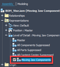
With this new Representation being active, select the components you wish to turn off, then right-click on one of them to Suppress. Leaving you with only the components you require to be visible in the Representation.
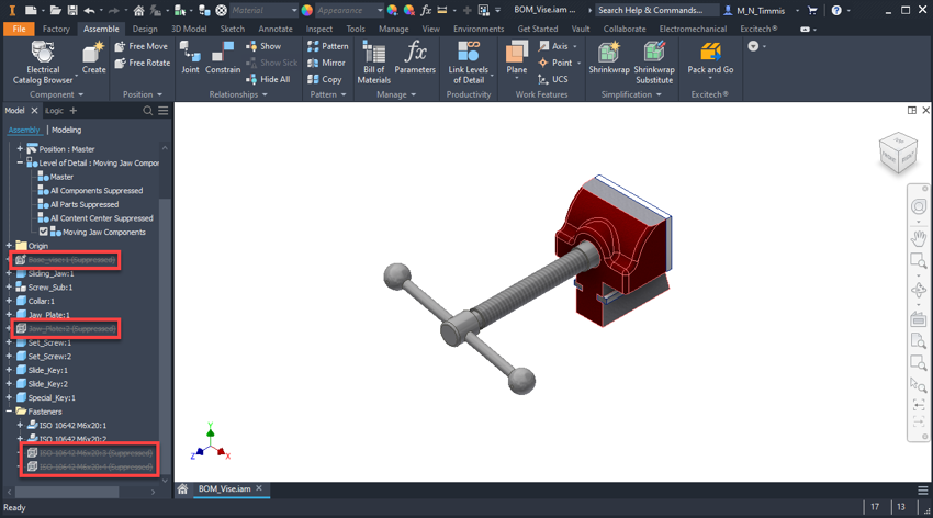
Once you have suppressed the required components, it is worth clicking save, to ensure this information is stored within the new Representation. Now you can double click on Master to see all components and the New Representation to see only the relevant components at that point. If you glance it your Assembly part counters (bottom right of the display) you will notice the numbers change when switching between your Level of Detail Representations. In this example, the total occurrence count drops from 21 to 17 between Master and Moving Jaw Component Representations, meaning less data is loaded within Inventor during this session!


Another useful Level of Detail Representation option is New Substitute > Shrinkwrap. This allows you to take a complete Assembly and choice options to generate a simplified single Part file. Which can then be used for sharing with others or activated as a Simplified Level of Detail within higher-level Assemblies.
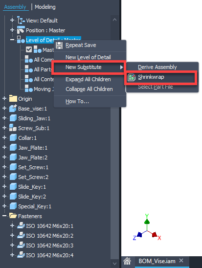
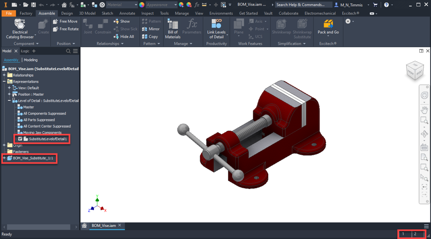
Following the completion of the Shrinkwrap process, you will find a new Level of Detail Representation, along with the generated Part within the Browser. Notice the total occurrence count has dropped from 21 to 1 within the Assembly.
Reusing Representations:
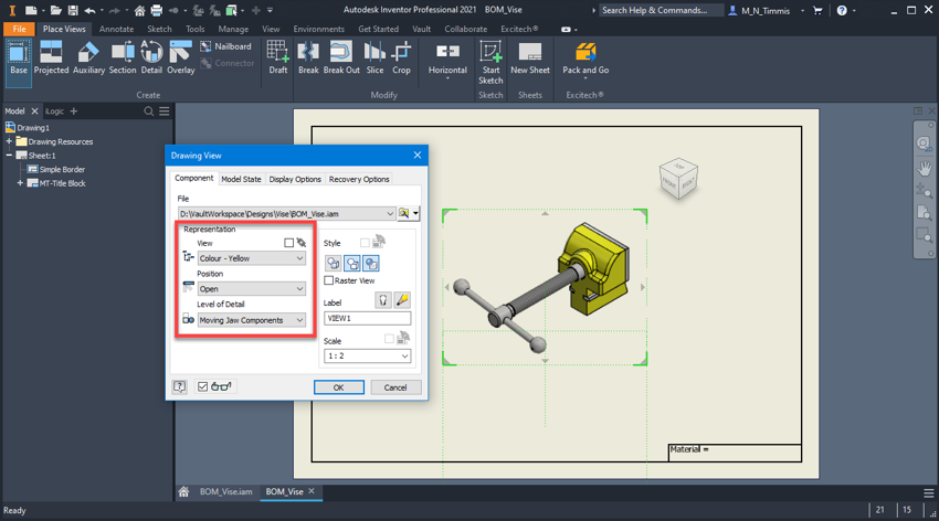
When it comes to reusing these Representations downstream, this can be done within both other Assemblies and Drawings. Within Drawings, all the Representations are available within the initial Place view dialogue. Where you can also use a mix of different Representations at the same time. For example, a View Representation for colour and a Level of Detail for turning certain components off. Please Note: Assembly section views do not come through to drawings, these would need to be added as a Section View.
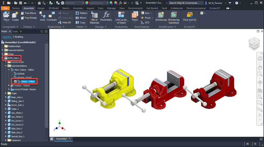
Within other Assemblies, once you have placed your Assembly containing the Representations, you can expand the tree to find and select the relevant Representations you require. It is possible to place the same Assembly within a higher level Assembly, all with different Representations, as shown in the example below.
For more tips and tricks, join me or my colleagues on one of our Revit training courses. Take a look at our full range of Autodesk Inventor training courses here.