
How AI Is Transforming Daily Work in Service Teams
Reduce downtime and improve service efficiency with AI-powered troubleshooting. Learn how service teams use ilean to solve problems faster and capture knowledge.
Geometric objects in AutoCAD can display in different patterns of dashes, spaces, dots, text and symbols.

This visual property is controlled by linetypes. While in AutoCAD you can find a wealth of linetypes that come with the default installation, in some occasions you may need to create your own. Therefore, understanding how to create linetypes is a useful tool and can be added to your AutoCAD course.
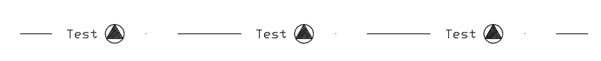
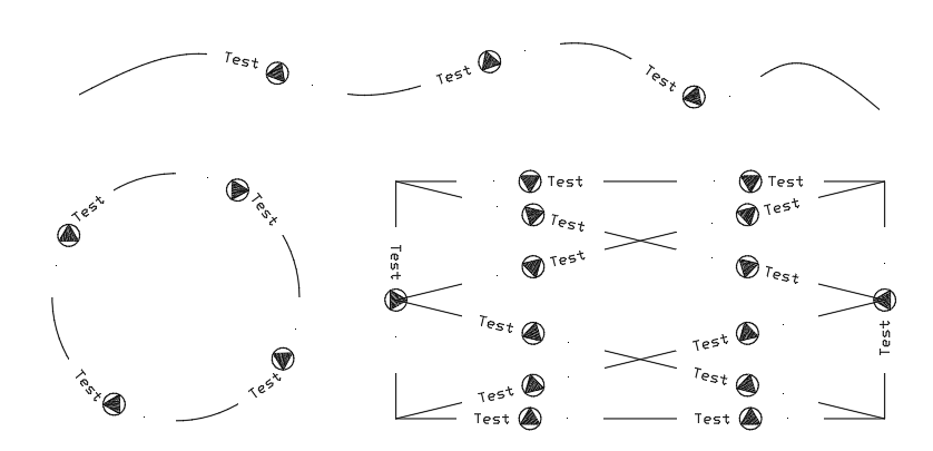
In this blog, we will progress step by step through an AutoCAD course exercise where we create a linetype containing both text and shape objects. The final linetype will look like the one shown below.
In order to incorporate geometry into the linetype other than text, dashes and dots, it will need to be included as a shape object. Consequently, we will start by creating a shape for the hatched triangle inscribed in a circle shown above.
As shape objects cannot contain a hatch, we will need to explode the hatch inside the triangle to convert it into lines. For this to work, we should have selected a pattern that is made up of lines (like ANSI31) and not a solid one. If the pattern is meant to look solid, make sure that you select a hatch pattern scale that is small enough.
We can now create the shape using the ‘Make Shape’ command that can be found in the slideout of the ‘Tools’ panel, under the ‘Express Tools’ tab of the ribbon. After picking a location to save the SHP file, follow the prompts in the command line. Note that an SHX file will also be created in the same folder.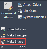
The next step is to draw the pattern of the linetype in model space in AutoCAD. The pattern must begin with a dash, that can be drawn in AutoCAD as a line. In regard to the text, it needs to be created as single line text as multiline text cannot be inserted in the linetype. To insert the shape, type SHAPE in the command line and then use the name that you gave it when you created it. Finally, we insert a dot using the POINT command.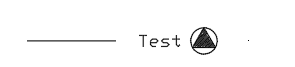
To create the linetype from the pattern, use the ‘Make linetype’ command from the ‘Tools’ panel of the ‘Express Tools’ tab of the ribbon. When asked to select a linetype file (*.lin), you can create a new one or select an existing one. Picking an existing file will not delete any of the preexisting linetypes in the file, it will just add the new linetype.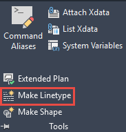
If you open the LIN file in a text editor, you will find that the linetype has been added as two lines of text that you can modify directly if you wish. The syntax is as follows:
In my example, you can find the pattern drawn in AutoCAD and the two lines of text that describe it in the LIN file. Note that the pattern starts with a dash (20) and finishes with a dot (0) and a final space (-10).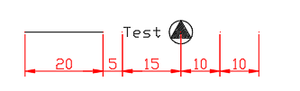

With the linetype being created, it can be loaded into AutoCAD and applied to different objects.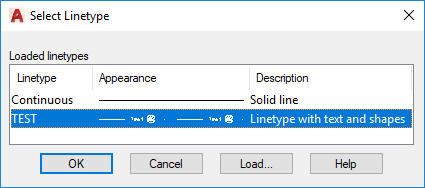
This example is just one area covered in an advanced, bespoke AutoCAD course.
If you would like to explore the different AutoCAD courses, we host at Symetri, take a look at our full list of AutoCAD courses.

If you would like to discuss your training requirements further please feel free to reach us on 0345 370 1500 or info@symetri.co.uk.
Reduce downtime and improve service efficiency with AI-powered troubleshooting. Learn how service teams use ilean to solve problems faster and capture knowledge.

Cybersecurity risks are not always caused by sophisticated attacks or major system failures. In many cases, risk builds quietly through everyday habits, overlooked processes, and limited visibility into where data is stored or how users interact with systems.

Learn how to reduce cyber risk through stronger security foundations. This month's bulletin covers home office security, legacy technology risks, vulnerability management, MFA, and cybersecurity best practices.