
How AI Is Transforming Daily Work in Service Teams
Reduce downtime and improve service efficiency with AI-powered troubleshooting. Learn how service teams use ilean to solve problems faster and capture knowledge.
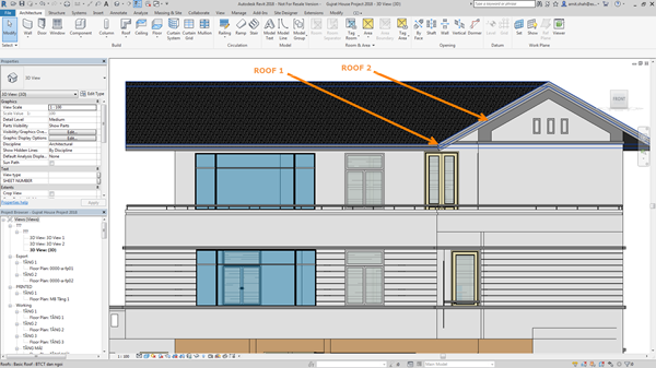
A quick tip to create a seamed metal roof in Revit 2018 should you need to represent standing seam metal roof ridges in 3D.
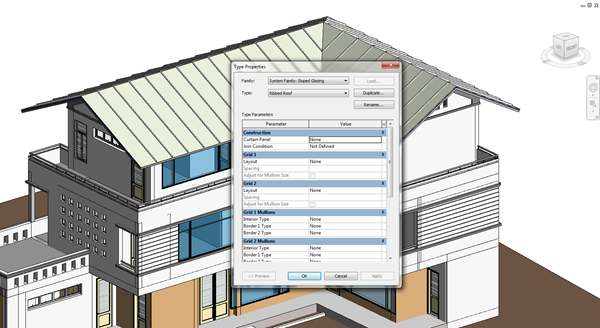
The Revit 2018 material for standing seam metal roofs has a surface pattern and an image with a bump map as a default. Most of the time this is a sufficent representation of a standing metal seam roof; the data and graphic representation is shown, and it will look fine in your construction documentation. However, when rendering, the default material for standing seam roofs does not come out so well in Revit 2018
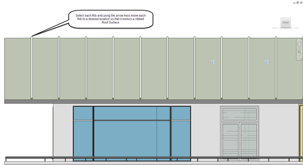
As a result, I've put together a quick trick that will help you render views of roofs that you have already created. The trick is simple; as you have already spent time modelling all of the ridges, valleys, hips etc, it makes sense to use them rather than duplicate efforts.
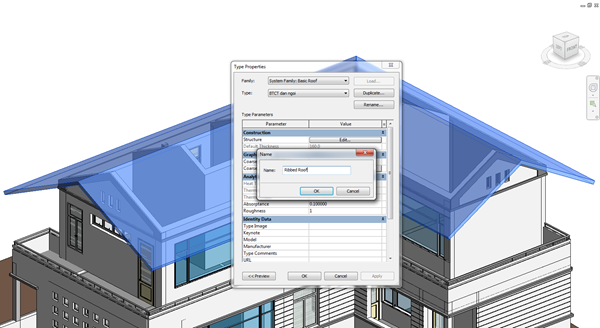
(Suggestion - at this point, you can customise and/or create your own profiles to be used as mullions that have the exact size and shape to it. The same applies for the horizontal and vertical grid alignments. For the purposes of demonstration, I have used the default profiles available.)
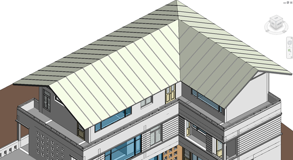
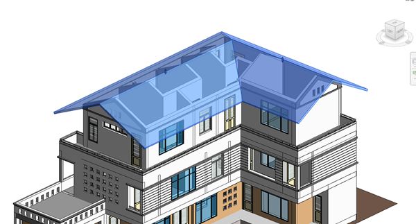
The final product should look like the figure below (based on the default isometric 3D view.)

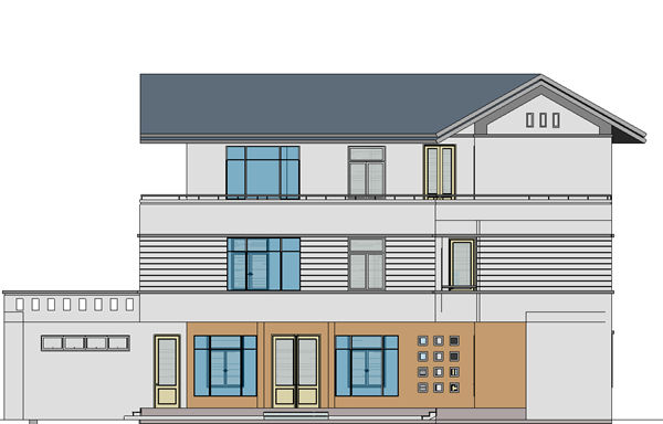
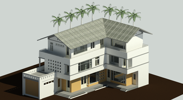
Or shown as a rendered view.
For more information on Revit 2018, please get in touch or visit our product page here.
Reduce downtime and improve service efficiency with AI-powered troubleshooting. Learn how service teams use ilean to solve problems faster and capture knowledge.

Cybersecurity risks are not always caused by sophisticated attacks or major system failures. In many cases, risk builds quietly through everyday habits, overlooked processes, and limited visibility into where data is stored or how users interact with systems.

Learn how to reduce cyber risk through stronger security foundations. This month's bulletin covers home office security, legacy technology risks, vulnerability management, MFA, and cybersecurity best practices.