What’s New in Inventor 2027: A Guide to the Latest Features
Consultant Jason Kelly explores the new 2027 features in Autodesk Inventor Professional. Including updates to the content center and Autodesk Assistant

The Revit Architecture training material used teaches a method which uses the Wall tool configured with its Type Function set to Soffit. Although it works and is a relatively simple solution, using the Wall tool means the bulkhead exists upon the `Wall’ category and not the `Ceiling’ category. So, when the Ceilings are turned off, this bulkhead will remain visible and will need to be turned off `By Element’.
Using the In Place Modelling capability of Revit Architecture, the bulkhead can be modelled in situ which means the `Ceiling’ category can be assigned to it.
Here’s a step by step guide on how to achieve an In-Place Bulkhead, which I would show within a typical Revit Architectural training course.
Note, however, this is in full Revit and cannot be achieved within Revit LT.
Firstly, I’m going to construct a 600 x 600mm Ceiling Grid set to a height of 3000mm.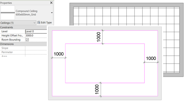
Then I’m going to `Edit Boundary’ to create a void offset by 1 metre from the walls within this ceiling. The raised ceiling, in the next section, will be drawn using the void as an outline.
I have added `Locked Dimension Constraints’ to the new loop to ensure the offset is maintained when any of the 4 walls are moved.
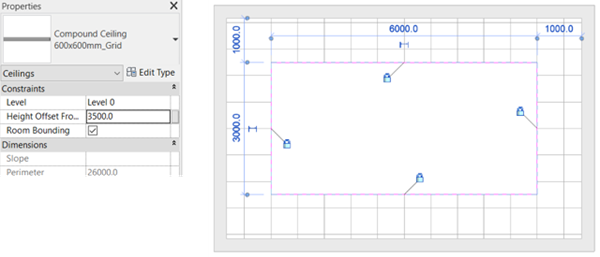
After finishing edit mode, I will load the Ceiling tool again followed by `Sketch Ceiling’ and trace around the void within the lower ceiling locking the `Alignment’ padlocks along the way. This ensures if the walls are moved, the new raised ceiling will automatically adjust. This ceiling will be 3500mm from Level 0.
After finishing edit mode, If I open the 3D and a Section view it will appear as follows: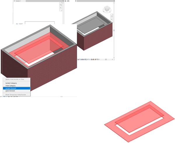
Now it is time to add the In-Place Bulkhead.
When working within a complex project it might be a good idea to `Isolate’ the 2 Ceiling elements to make it easier to see and model in the desired area.
Once I load the `Model In-Place’ tool I can assign the `Ceiling’ category to it and then provide a name: `Bulkhead’.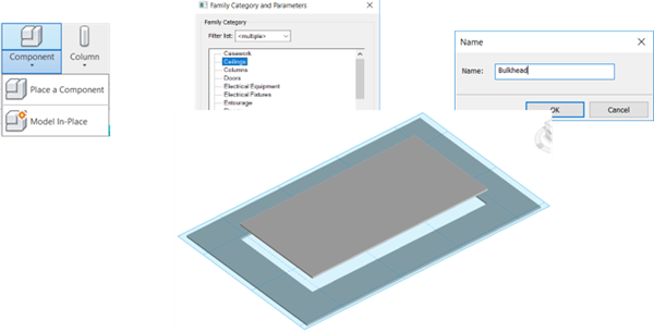
After this had been done, the modelling tools can be utilised. For this, I am going to create an Extrusion. But first, I will set the Work Plane to the top face of the lower ceiling. To confirm it is in the desired location `Show Work Plane’ is available. After selecting Extrusion I’m going to sketch a loop around the opening and offset this by 52mm and set the `Extrusion End’ to 500.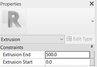
So that the 52mm thickness will be maintained if the walls are moved, I will add a `Locked Dimension’. Then select `Finish Edit Mode’.
The result should look like this: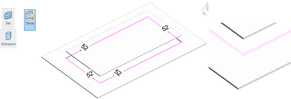

Now I’ll finish the model by selecting ![]()
The next task is to Align ![]() and lock the In-Place Bulkhead to the upper and lower ceiling to ensure it automatically updates if either of these are raised or lowered. In both instances, remember to select the ceiling first before selecting the Bulkhead. Then lock the padlock.
and lock the In-Place Bulkhead to the upper and lower ceiling to ensure it automatically updates if either of these are raised or lowered. In both instances, remember to select the ceiling first before selecting the Bulkhead. Then lock the padlock. 
Well that should be it. If all has gone to plan, if the Walls are moved the Ceiling and Bulkhead will self-adjust too and if the either of the Ceilings have their `Height Offsets’ altered, the Bulkhead will alter too.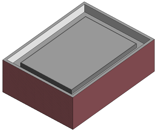
For more ornate bulkheads try using the `Solid Sweep’ tool.
Ceiling Plans are normally covered on day 3 of our Revit Architectural Fundamentals training course. View the full agenda HERE.
Take a look at our full range of Revit training courses HERE:
Consultant Jason Kelly explores the new 2027 features in Autodesk Inventor Professional. Including updates to the content center and Autodesk Assistant
Vault 2027 release includes improved property handling, stronger PLM connectivity, and the introduction of the AI‑powered assistant.
AutoCAD 2027 introduces new tools to improve collaboration, drawing accuracy, and productivity, including Autodesk Forma data management integration, Geometry Cleanup, and the AI‑powered Autodesk Assistant. In this guide, we highlight the key AutoCAD 2027 updates and explain how they support more efficient, connected workflows for design teams.