
How AI Is Transforming Daily Work in Service Teams
Reduce downtime and improve service efficiency with AI-powered troubleshooting. Learn how service teams use ilean to solve problems faster and capture knowledge.
If you need help in creating iBox components within the Woodwork for Inventor Sheet Metal environment follow the workflow explained in the blog.

The workflow you require when attempting to generate iBox components with sheet metal components is very similar to the standard iBox workflow but materials will need to be applied in a different format than the normal workflow.
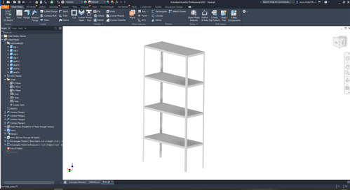
In this example we need to create a standard shelving unit of different sizes with no ‘Joinery’ elements used:
The first step is the most important and is based on design requirements. Create the model as usual within the Autodesk Inventor Sheet metal environment however, all components will need to be generated as new bodies using the sheet metal tools. It should also be parametrically driven based on three parameters; height, width, and depth.
Note. Make sure you name these parameters as this will help identify them when authoring the iBox.
This is the same as working within the skeleton dress-up tool, but this process is completed manually in sheet metal. Also please note if you are looking to save this to the iBox library make sure you are in the iBox library project and saving it to the appropriate location.
Save the base file, again you will need to utilise this so make sure you are saving it to the appropriate location. Generate all solid bodies into parts by using the ‘Make Components’ tool, making sure you leave checked ‘Insert components in target assembly’.
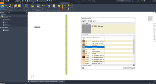
Save the new assembly file and make any necessary ‘joint’ changes at this level. At this point don’t assign the material to each component.
To assign material open up each sheet metal part individually, and generate a flat pattern. This is because at the folded model level the woodwork options will be greyed out. Activate the flat pattern and assign a woodwork appearance to the flat pattern. There is a standard sheet metal material in the ‘Boards’ area.
Update and save the assembly.
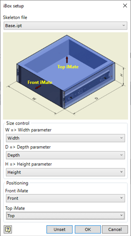
Place in the original base part file and ‘ground and root’ the part. At this point, it is best practice to rename the model to @Skeleton.
Assign iMates to the assembly component (Top, Front, Left, and Right). These will need to be all ‘Flush’.
In the Manage ribbon, there is an iBox Author option. Choose this and fill out the form. The skeleton file will be the base component placed earlier.
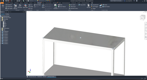
This assembly will now be an ibox component and you can use it in any standard layout. Here is an example:
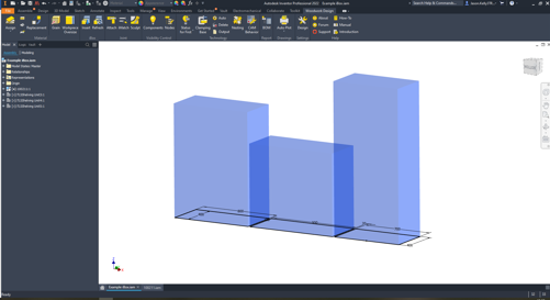
Three boxes have been generated and converted to skeleton bodies within the skeleton dress up environment. This part with the three bodies has been placed into an assembly file.
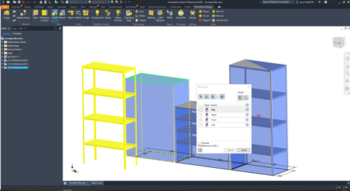
The iBox was inserted chosen from the iBox library. Save the new assembly to the appropriate location using the prompted save box. Select opposing iMates using the box layout generated.
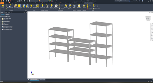
The newly saved component with all part files saved as new components has been generated and now fit the outer perimeters of the box.
We hope you found this tip useful.
If you would like to brush up on your Woodwork for Inventor skills and make the most of its tools, explore our Woodwork for Inventor course.
For more information on Woodwork for Inventor or any of our Autodesk Software, please contact us by emailing info@symetri.co.uk.
Reduce downtime and improve service efficiency with AI-powered troubleshooting. Learn how service teams use ilean to solve problems faster and capture knowledge.

Cybersecurity risks are not always caused by sophisticated attacks or major system failures. In many cases, risk builds quietly through everyday habits, overlooked processes, and limited visibility into where data is stored or how users interact with systems.

Learn how to reduce cyber risk through stronger security foundations. This month's bulletin covers home office security, legacy technology risks, vulnerability management, MFA, and cybersecurity best practices.