
How AI Is Transforming Daily Work in Service Teams
Reduce downtime and improve service efficiency with AI-powered troubleshooting. Learn how service teams use ilean to solve problems faster and capture knowledge.
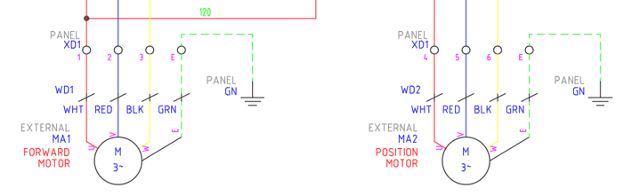
In this blog article, we will take a look at how we can show our terminal information within an electrical design and how we can extract this information for device termination, display cable/wire information, and help downstream processes such as procurement.

We can display terminal information within a schematic layout by inserting a terminal symbol from the icon menu and assign the relevant information to that terminal such as installation/location code, tag strip identification, terminal information and catalogue information.
This information can then be extracted into a graphical or table layout on a terminal drawing within the electrical project. We use this layout to show cable/wire information, device information, internal jumper layouts and catalogue information. Additional terminal accessories can be added at this stage such as terminal holders, spacers and covers by assigning the catalogue information.
Note: All catalogue information will require an associated block defined within the footprint database to display the component within the graphical layout.

If you are looking to use a specific component that does not exist within AutoCAD Electrical. It is very simple to create your own symbols and footprints by using the symbol builder feature and selecting the specific component, i.e. parent component, child component, terminal, panel footprint, and panel terminal.
If you would like further information on the benefits of using AutoCAD Electrical for your electrical design, feel free to contact us at Symetri to arrange a consultation with one of our electrical specialists. We offer scheduled AutoCAD Electrical essentials training and bespoke training tailored to your requirements to help you work smarter for a better future.
Reduce downtime and improve service efficiency with AI-powered troubleshooting. Learn how service teams use ilean to solve problems faster and capture knowledge.

Cybersecurity risks are not always caused by sophisticated attacks or major system failures. In many cases, risk builds quietly through everyday habits, overlooked processes, and limited visibility into where data is stored or how users interact with systems.

Learn how to reduce cyber risk through stronger security foundations. This month's bulletin covers home office security, legacy technology risks, vulnerability management, MFA, and cybersecurity best practices.