
Securing the Modern Workplace
Learn how to protect your organisation from QR code phishing, adopt passkeys securely, and manage AI note-takers with the latest IT security advice from Symetri.
You can perform surface analysis in Civil 3D based on different parameters, such as elevations or slopes.
A number of ranges will be generated, and a colour assigned to each of them, which will then be displayed in the surface using the surface style. A typical use of this functionality is to display various depths of cut and fill in different shades of red or green colours.
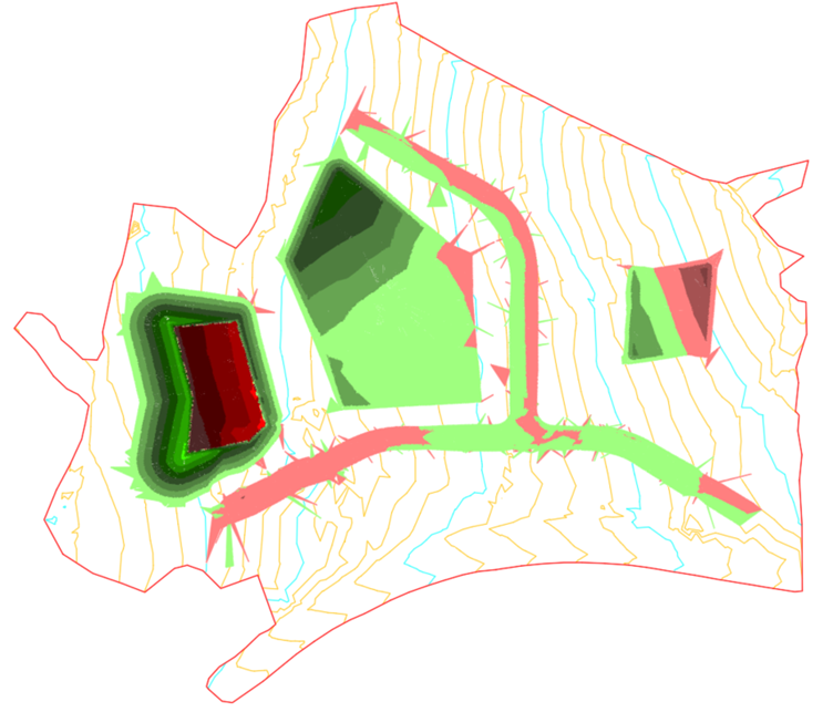
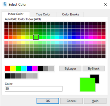
When you initially create the intervals, a colour scheme will be automatically generated according to the surface style. You can then change the colour and the lower and upper bounds for the ranges by clicking on the corresponding cells.

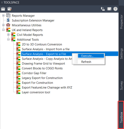
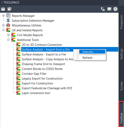
We are now going to use a tool from the UKIE Country Kit that allows you to export the ranges to an external file that can then be imported into other drawings. From the Toolbox tab in the Toolspace palette, access UK and Ireland Reports -> Additional Tools -> Surface Analysis – Export to a File and execute that tool from the right click menu as shown below. You will then be asked to select the surface whose analysis you want to export and to specify a name and a location to save the external file.
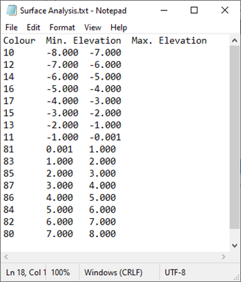
The file that was created in the previous step is simply a text file and it can be opened and modified in a text editor if needed. The first column contains the AutoCAD Colour Index and the next two columns represent the lower and upper bounds of the range. Different columns are separated by tab characters.
From the Toolbox tab in the Toolspace palette, execute UK and Ireland Reports -> Additional Tools -> Surface Analysis – Import from a File, browse to the text file and finally select the surface where you want to apply the analysis ranges. Note that this tool will only import the ranges, you will still need to select a surface style that will display that analysis, 2D Solid Cut and Fill in this instance.
I hope you found this useful. For further guidance on Civil 3D, explore our training courses here.

Learn how to protect your organisation from QR code phishing, adopt passkeys securely, and manage AI note-takers with the latest IT security advice from Symetri.

Reduce downtime and improve service efficiency with AI-powered troubleshooting. Learn how service teams use ilean to solve problems faster and capture knowledge.

Cybersecurity risks are not always caused by sophisticated attacks or major system failures. In many cases, risk builds quietly through everyday habits, overlooked processes, and limited visibility into where data is stored or how users interact with systems.