
How AI Is Transforming Daily Work in Service Teams
Reduce downtime and improve service efficiency with AI-powered troubleshooting. Learn how service teams use ilean to solve problems faster and capture knowledge.
Creating and modifying sloped piping can sometimes be a bit of challenge in Revit. This blog is going to look at some of the various tools and options that will make things a little easier.

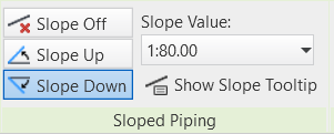
1. Use the Sloped Piping tool.
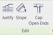
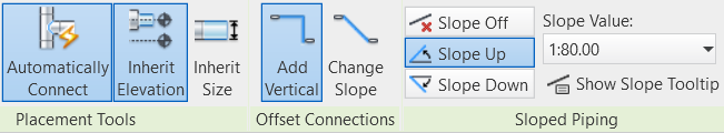
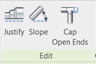
2. The edit Slope tool, which is accessed from the ribbon when you have picked a piece of pipe.
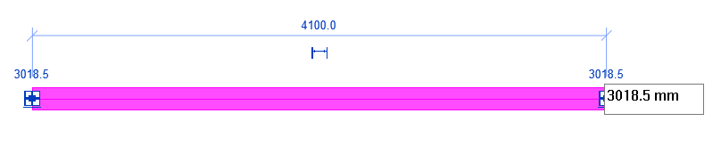
3. Edit a slope value of an existing pipe from the screen.
4. Edit the end or start elevation values of an existing pipe.
These options can all work well with just a single piece of pipe but if you need to join a sloping pipe together then consider using some of the other pipe creation tools available in Revit.
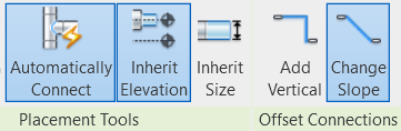
When creating a new section of pipe, the default Offset Connection is Add Vertical. Using this tool when connecting pipes at different elevations will result in a vertical rise or drop from one elevation to the other. However, if the Offset Connection is set to Change Slope the result will be a slope from one elevation to the other.
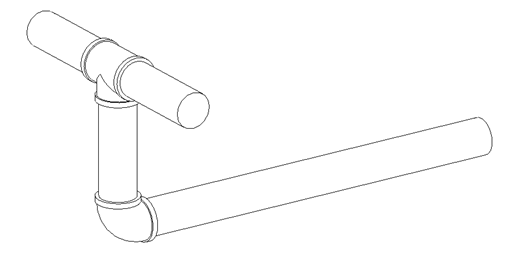
Using Add Vertical with an elevation change of 500mm
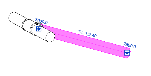
Using Change Slope with an elevation change of 500mm
Using this tool results in a sloped pipe with defined start and end elevation rather than a specific slope value.
To achieve a result where two sloping pipes come together while defining a specific slope value, use the Sloped Piping tool and the Inherit Elevation option together, as shown below.
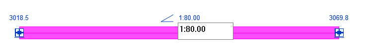
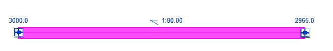
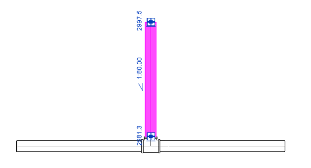
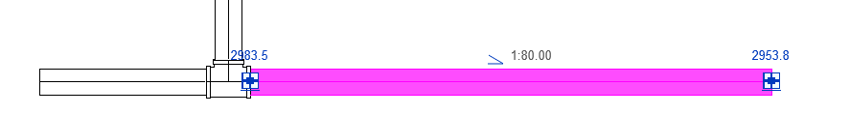
Create an initial section of pipe with a defined slope using the slope tool. Here we are using Slope Down at 1:80.

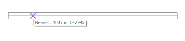
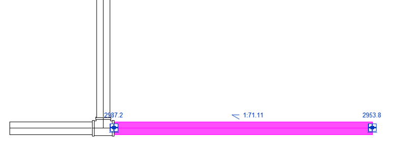
To connect a branch pipe also sloped at 1:80 simply use Inherit Elevation and draw away from the first pipe with the slope set to Slope Up.
As the cursor is placed over the existing pipe, the use of Inherit Elevation will automatically pick up the changing elevation along the length of the pipe.
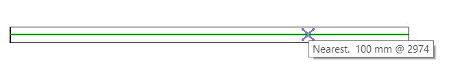
Result, branch pipe sloping up from the main pipe by using Inherit Elevation.
We have considered some of the ways that sloped piping can be created in Revit, but how about changing that slope afterwards?
At the start of this article, we looked at methods that can be used to create and edit the slope of a single section of pipe, but it does become more difficult as the size of the pipe layout grows.
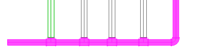
Below is a main pipe whose slope value needs editing but is connected to a branch pipe.
1. Select the main pipe and the fitting to the branch pipe.
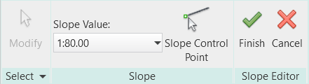
2. Choose the required slope from the Slope Editor and select the green tick finish button.
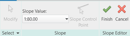
3. This results in a change to 1:80 to the slope of the main pipe that also includes the fitting to the branch pipe.
4. For multiple branches use the same technique. Select the main pipe and all branch fittings and choose the slope value from the Slope Editor.

As the pipe layout becomes more complex something will have to give. What is selected will determine the outcome. The selection option shown below will alter the slope of the main pipe, whilst maintaining the end elevation of the branch pipes. However, the slope value of the branch pipes will alter and may need adjusting.
Selecting all pipes will have the effect of setting a common slope value, but the end elevations of the branch pipes will change.
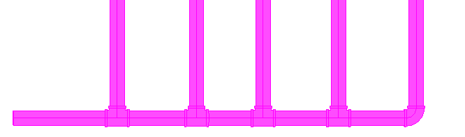
In summary, when working with sloped pipes in Revit, you will have to be specific about what you select and bear in mind, the more complex the layout the greater likelihood that connected elements may be affected.
One final word. Don’t underestimate the humble end cap. Sometimes simply removing a strategic end cap could result in your slope editing being successful.
If you would like further information on Revit MEP, feel free to get in touch at info@symetri.co.uk or contact via the form below.
Find out more about our Revit Training courses here.
Please submit your enquiry here and a member of our team will get in touch.
Alternatively call 0345 370 1444
Reduce downtime and improve service efficiency with AI-powered troubleshooting. Learn how service teams use ilean to solve problems faster and capture knowledge.

Cybersecurity risks are not always caused by sophisticated attacks or major system failures. In many cases, risk builds quietly through everyday habits, overlooked processes, and limited visibility into where data is stored or how users interact with systems.

Learn how to reduce cyber risk through stronger security foundations. This month's bulletin covers home office security, legacy technology risks, vulnerability management, MFA, and cybersecurity best practices.