
How AI Is Transforming Daily Work in Service Teams
Reduce downtime and improve service efficiency with AI-powered troubleshooting. Learn how service teams use ilean to solve problems faster and capture knowledge.
Graham Mansfield discusses his top five reasons why making the leap from 2D CAD to Woodwork for Inventor must be the best choice today.
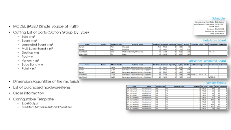
For anyone using 2D cad such as AutoCAD today to generate setting out drawings for manufacture, there is a huge time burden on the generation of cutting lists, veneer schedules and project documentation. The introduction of parametric 3D software automates the creation of Bill of Materials by simply exporting parameters for length, width and thickness as well as component quantities with descriptions. However, this approach does not really meet the needs of the setting out joiner. The reason is quite simple, that the way the panels are manufactured include covers, balancer and edge banding or veneers which ultimately effect the part size. Each has its own thickness, so how can you report this without modelling everything or entering manually into a spreadsheet. Woodwork for Inventor handles this easily by allowing you to assign materials that contain this size information with a database that automatically calculates the workpiece size. Automatically synchronised every time the BOM specification is started you which can quickly export to comprehensive schedules using Microsoft Excel templates.
 Reason 2 - Standardised Library Parts
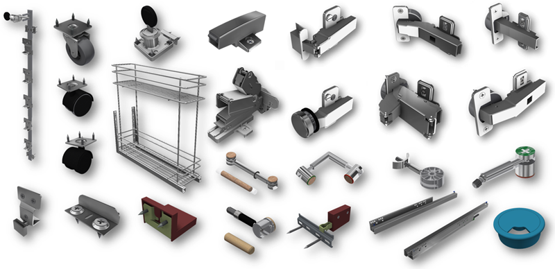
Library parts are a great way to assist in value engineering and standardisation which is good practice in design. With woodwork for Inventor we can define cut-outs and pilot drilling within our parts as well as pre-assigning assembly connections via inventor’s own iMate technology. Simply follow the prompts to apply multiple library parts to your assembly. Traditionally each part would be modelled to be included in the BOM specification. However, by using a few custom Woodwork for Inventor parameters we can define several additional components such as screws, washers, clips that can be included and totalled in the specification.
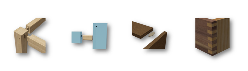
When it comes deciding how to construct your product by either screw and batten or Domino, Biscuit or Minifix for example, the 2D setting out draughtsperson tends to omit this completely from the drawing, leaving the task for the CNC programmer or manufacturing team to decide what’s best. This really is not efficient because it's important to streamline this process to make sure when the job hits production it can be processed as quickly as possible. To assist the creation of all cut-out and hole details, the Woodwork for Inventor sculpt tool can work in two ways. The first obvious way is to remove material such as a cut-out, but also it is possible to add material which means we can define wood joints. Again, everything is synchronised back to the BOM specification. When creating these drillings, we can generate automatically across the entire assembly in a single pass.
Drawings for manufacture are the bane of every setting out joiner's life. Creating detail drawing packs is a requirement usually exclusively reserved for pre-and post contract approval and when no automation to CNC is available they are needed more than ever to convey design intent, specific size, drillings, and General Arrangement. With the introduction of 3D packages that allow for the creation of automatic 2D views, “it's the details that take the time”. This is where the Auto Plot tool assists.
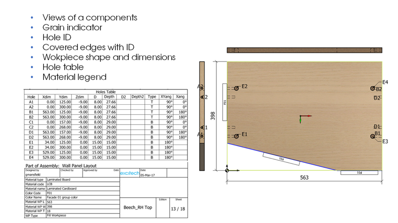
From your choice of template, you can automate the generation of your component part drawings to contain all relevant part and workpiece details, dictate view styles, grain direction and any edge banding used. All of the views get the choice to have overall sizes and work piece sizes dimensioned and annotated with hole drilling information as well as material specification. A typical drawing bundle takes just a few minutes to generate.
Although an additional module, Woodwork for Inventor CAM can accelerate your design to manufacturing process by allowing you to complete your CNC output directly from your CAD system. No longer do you have to break the process that can potentially be the bottleneck to getting the job out of the door. Over the past few years, the team behind Woodwork for Inventor have been busy adding more post processor support. In the UK, machine manufacturers such as Homag with Woodwop and SCM with Xilog Maestro appear to be incredibly popular but we cater for many others.
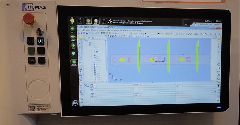
If you are like many, who have invested in CNC and would like to speed up the delivery of CNC programs directly to these software systems then this is a clear and easy decision to be made.
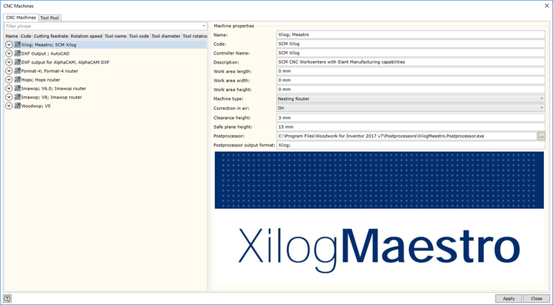
Processing is incredibly simple by either manual or automatic processing at the Assembly or part level. Choose your CNC Output, Xilog Meastro for example.
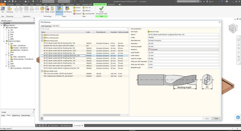
Setup your tool library.
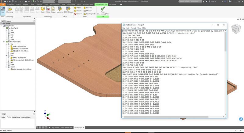
Process Top & Bottom faces of the panel and you will be able to generate two programs automatically. This feature facilitates acceleration of the CNC program preparation and prevents potential errors.
Even if you were using other CAD systems it is possible to easily process models imported into Autodesk Inventor such as (STEP, IGES, ACIS, AutoCAD, Solid Works, CATIA, etc.) as well. You simply need to assign a Woodwork for Inventor material for an imported model and you will be able to work with the part in the Woodwork for Inventor CAM environment.
Currently, Woodwork for Inventor has post-processors for the following systems:
Reduce downtime and improve service efficiency with AI-powered troubleshooting. Learn how service teams use ilean to solve problems faster and capture knowledge.

Cybersecurity risks are not always caused by sophisticated attacks or major system failures. In many cases, risk builds quietly through everyday habits, overlooked processes, and limited visibility into where data is stored or how users interact with systems.

Learn how to reduce cyber risk through stronger security foundations. This month's bulletin covers home office security, legacy technology risks, vulnerability management, MFA, and cybersecurity best practices.