
How AI Is Transforming Daily Work in Service Teams
Reduce downtime and improve service efficiency with AI-powered troubleshooting. Learn how service teams use ilean to solve problems faster and capture knowledge.
With Naviate Infrastructure for Civil 3D, you can easily configure your environment to help users manage their assemblies and sub-assemblies, and apply corridor settings consistently across your projects.

There’s no doubt that Civil 3D has some great functionality, but one area where it’s lacking is in managing your organisations content for corridor modelling. We can create our own catalogues for Pipe Networks and Pressure Pipe Networks, and we have some good options for managing styles, but for assemblies and sub-assemblies, not so much.
With Naviate Infrastructure for Civil 3D, you can easily configure your environment to help users manage their assemblies and sub-assemblies, and apply corridor settings consistently across your projects.
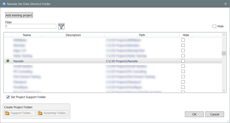
Naviate settings and content are stored in Naviate support files which is created on each users own PC in a public folder. When you need to control standards for a particular project, you can create project support folders that will reside in your Data Shortcut project folder. This allows you to control project standards and global standards separately.
Sub-assemblies need to be imported into Civil 3D before they can be used, and this results in them being added to a Tool Palette. With standard sub-assemblies, Country Kit sub-assemblies and perhaps any that you may have created yourself, you can end up with many tool-palette tabs. If you’re the CAD or BIM Manager then you can of course create tool palettes for your users that bring together the sub-assemblies you want them to use, but this all needs managing and distributing, adding to the management overhead.
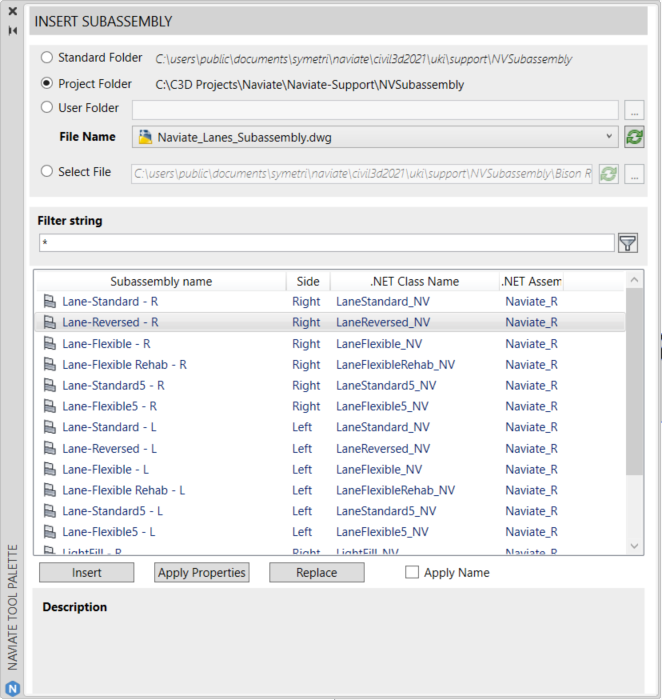
Naviate includes a simple solution for making collections of sub-assemblies available to your users. The sub-assemblies still need to be imported, but you can group the sub-assemblies that you want them to use in a Civil 3D drawing, and place the drawing in the support folder, your project folder, or any other library folder location.
Using the Naviate Insert Subassembly command, a user can select the library .dwg file, and then choose from a list of available sub-assemblies. They can then insert the sub-assembly, replace an existing sub-assembly, or update a subassembly to reset the subassembly parameters. It’s simple to use and a great way to make it easy for users to keep to the approved sub-assemblies for a project.
Taking this a step further, Naviate has a system for managing published assemblies. Let’s suppose you have a project where the client requires you to comply with certain standards of construction. You can ensure your users keep to the guidelines by creating the assemblies that are required in advance, and then “publishing” them.
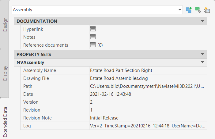
When you use the Naviate Export/Publish Assembly command to publish an assembly, you are adding version and revision control to the assembly, and you can publish the assembly drawing to either the standard support folder, or to a project support folder.
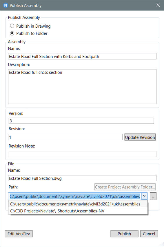
Publish in Drawing is used when you are editing an assembly drawing you’ve already created, and Publish in Folder is used to write an assembly out of your current drawing to a new library drawing.
Each time you publish, the Version number is incremented. You can also increment the Revision number when required. The Version is typically incremented when a change is made to the parameters of an assembly, whereas a Revision is incremented when changes are made to the construction of the assembly (adding or removing sub-assemblies).
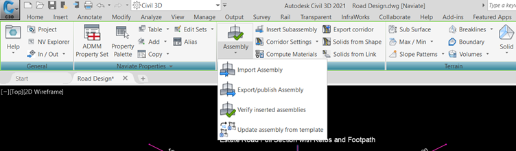
When you import an assembly using Naviate, property data saved on the assembly records the version number, revision number and the path to the assembly.
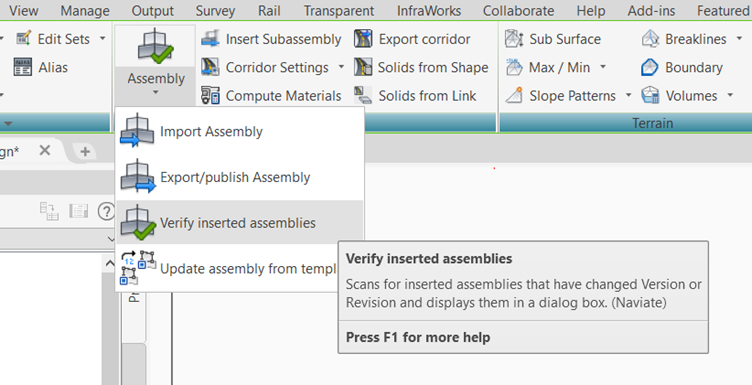
This information allows us to check whether we have the latest version of an approved assembly, using the Verify Inserted Assemblies command.
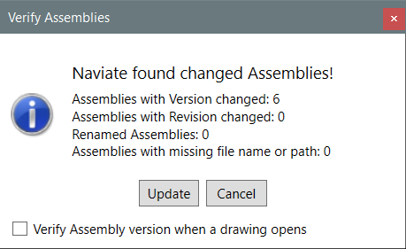
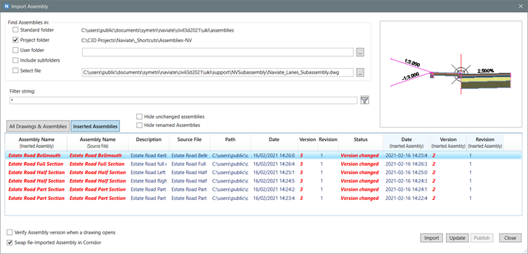
Choosing Update in the pop-up message will open the Import Assemblies dialog, where you review the revision information and select assemblies to update. The corridor can be edited automatically to include the revised assemblies, which is useful when you may have renamed the assembly in the drawing. You can also opt to check all assemblies automatically when a drawing file is opened.
When you need to have control over the assemblies that are used for a particular client, or for a unique project, then this tool is invaluable for ensuring all of your models are created to the correct standards.
One of the tools I like the most, and which I think is a huge time-saver, is Import Corridor Settings.
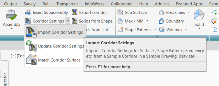
When you are modelling your corridors, you generally choose a corridor Code Set Style that shows you the feature lines and the links, so you can see how the corridor is constructed. When you are making changes constantly to the corridor, keeping the insertion frequency large reduces the time to rebuild the corridors, helping you to work faster. Then, you’ve finally finished all of your edits, and you need to make the corridor presentable for use on your construction drawings. This means increasing the frequency, applying and probably editing a code-set style to show the detail you need, and applying slope patterns for your embankments. All of this takes time, and if you’ve got multiple corridors to edit, can be very painful – especially if you’ve got to add slope patterns to all of the regions. And of course, you may also need to create corridor top and formation surfaces.
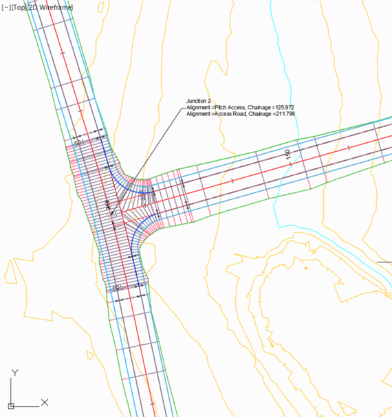
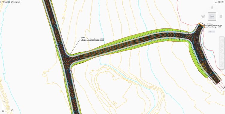
In the example above, the corridor is shown using styles for editing. Using the Import Corridor Settings command, you can update your corridor to match the settings saved on a corridor in a library drawing. You can have multiple examples of corridor settings, saved in one or more drawing files, and these can be stored in the support folder or the project support folder.
The image below shows an example corridor saved in the project support folder, that has insertion frequency, code-set styles, corridor surfaces and slope patterns defined. Using this template, we can update any corridor in our drawing.
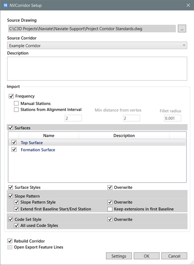
In the Setup dialogue, you can choose which aspects of the corridor you wish to apply settings to, and you can save the settings for re-use.
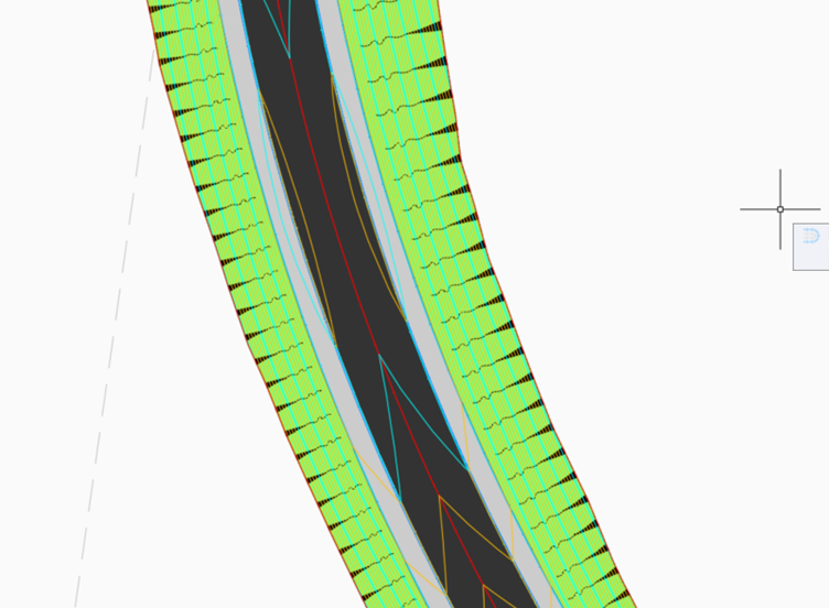
After applying the settings, the design corridor now looks like this:
The best part for me is I don’t have to pick lots of feature lines to get the slope symbols on the corridor. What a result.
You can check out the features of Naviate Infrastructure for Civil 3D and download a trial version from here.
Reduce downtime and improve service efficiency with AI-powered troubleshooting. Learn how service teams use ilean to solve problems faster and capture knowledge.

Cybersecurity risks are not always caused by sophisticated attacks or major system failures. In many cases, risk builds quietly through everyday habits, overlooked processes, and limited visibility into where data is stored or how users interact with systems.

Learn how to reduce cyber risk through stronger security foundations. This month's bulletin covers home office security, legacy technology risks, vulnerability management, MFA, and cybersecurity best practices.