Create a Formation Surface for a Platform in Civil 3D

Illustrating a workflow for a typical Civil 3D scenario

Autodesk's Civil 3D has some powerful tools for earthworks, through the use of surfaces and grading objects. Designing a platform can be a typical scenario for civil infrastructure professionals, so in this example, I'll illustrate a workflow for this. 

For this scenario we want to design a platform on a survey we have for the existing ground (EG). We need to discard the upper layer of topsoil from the EG. There is also a minimum depth from the finished platform to underside that must be met. Our goal is to combine this information to obtain a surface with the levels of the proposed formation, which will be the starting point for the fill to take place. 
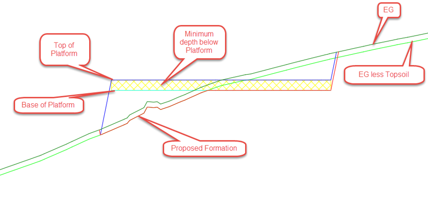
To establish that surface, we need to select the minimum level from the Base of Platform and the EG, less Topsoil surfaces. If we could take only the cut and isolate it from the fill between those two surfaces, we could get the proposed formation by combining the EG less Topsoil surface with the cut obtained as previously described.

There are several approaches to handle this; some of the key approaches have been detailed below: 
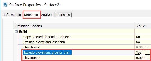
  1. Volume Surface: Create a volume surface between Base of Platform and EG, less Topsoil. Then exclude elevations greater than 0 in the Surface properties. This results in a surface with cut only, which means that this option cannot be used in the volume surface directly. To complete this approach, extract the triangles from the volume surface (Surface Contextual Ribbon > Extract from Surface > Extract Objects) and then create a new surface from those triangles.
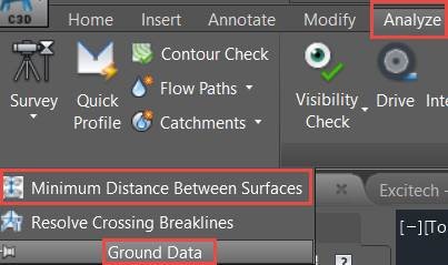
  2. Polylines: Draw polylines for the intersection of both surfaces (Base of Platform and EG less Topsoil) using the Minimum Distance Between Surfaces command (from the Civil 3D Ribbon > Analyse tab > Ground Data Panel - expanded), and use the polylines that enclose fill areas as Hide boundaries.
  3. Calculate Intersections: Compute the intersection between both surfaces as per point 2, then create grading groups to complete the surface. 

The third method, Calulate Intersections, allows accurate control of the slopes by grading objects. To complete this method, simply perfom the following steps: 
  • Create a surface for the EG from the survey data. 
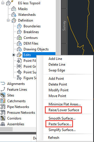
  • Create an EG less Topsoil surface by pasting the EG surface into it and offsetting it vertically by the topsoil depth. 

  • Create a grading group for the platform, selecting EG less Topsoil as the target surface. A surface then needs to be attached to the grading group. 

  • Create a Base of Platform surface by offsetting the surface attached to the grading object by the minimum depth below platform. 
  • Using the Minimum Distance Between Surfaces command, compute the intersection between the Base of Platform and the EG less Topsoil surfaces. 

  • Convert the polyline from the previous step into a feature line and complete the area in cut with another grading group (and an attached surface), targeting the EG surface this time. You will also need to place it in a different site, to avoid interaction with the top of the platform.

  • Finally, merge all of the surfaces together by pasting them into a new surface and applying boundaries accordingly. An additional grading object can be added to tie in the EG less Topsoil and the EG surfaces.

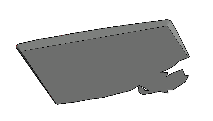
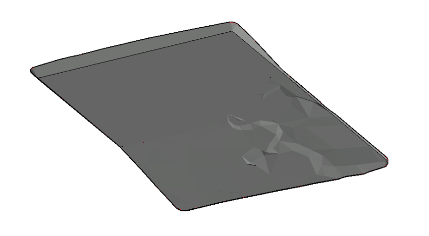
The final Proposed Formation surface in Civil 3D is shown in the object viewer, as per the below illustration. 
This is just one area that Autodesk's Civil 3D focuses on. For more information on how Civil 3D can help you improve project delivery, maintain more consistent data and processes, and respond faster to project changes, then please get in touch. You can also find a range of webinars on this software on our Civil 3D products page as well as details on how the latest updates can improve your workflows. 

Blog

Paths to Net Zero: Insights for Sustainable AEC

10 December 2024

As the built environment sector accounts for nearly 40% of global CO₂ emissions, achieving net-zero carbon has evolved from aspiration to necessity. In response, Symetri hosted the Paths to Net Zero: Insights, Technologies, and Solutions webinar series in September 2024. This article distils key takeaways from the series, offering a snapshot of challenges, trends, and impactful approaches shaping the future of decarbonisation in the AEC industry. 

Learn more
Blog

Harnessing the Power of Technology: Insights from Symetri

26 November 2024

Symetri is dedicated to helping businesses thrive in a rapidly evolving technological landscape. From leveraging AI in Microsoft Teams to maximising the potential of Microsoft 365 and addressing the critical impacts of IT downtime, understanding and implementing the right tools and strategies is key to success. Below, we explore three significant areas shaping the modern workplace.

Learn more
Blog

What is an LCA? 3 Examples of Life-Cycle Assessments in Building Projects

11 November 2024

A Life-Cycle Assessment (LCA) is a powerful tool used to measure the complete environmental impact of a building project. It evaluates the carbon footprint and other environmental effects throughout a building's life, across four key stages: production, use, end-of-life, and beyond. Below are three examples of how LCAs can guide decisions for more sustainable building projects.

Learn more