
Securing the Modern Workplace
Learn how to protect your organisation from QR code phishing, adopt passkeys securely, and manage AI note-takers with the latest IT security advice from Symetri.
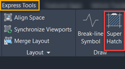
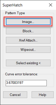
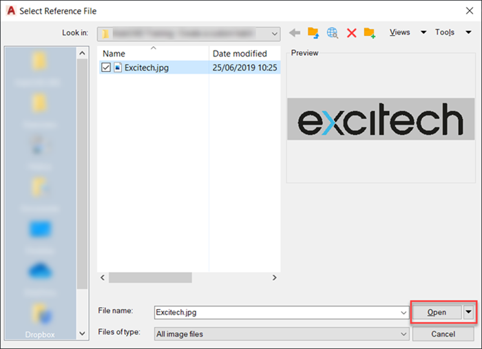
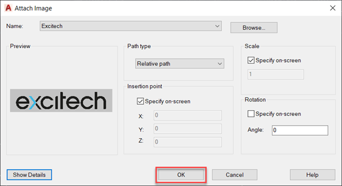
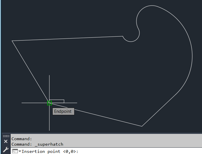
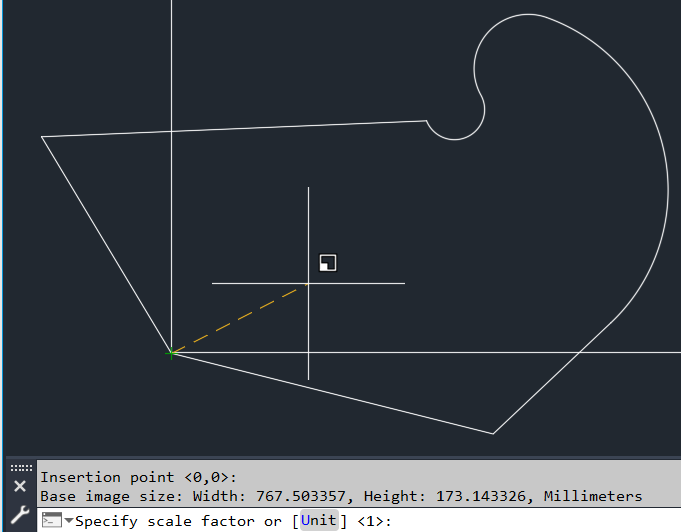
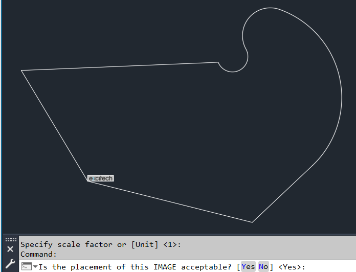
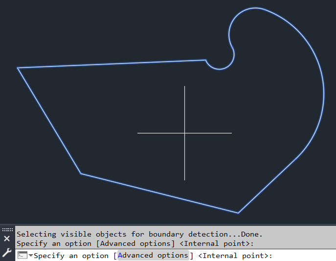
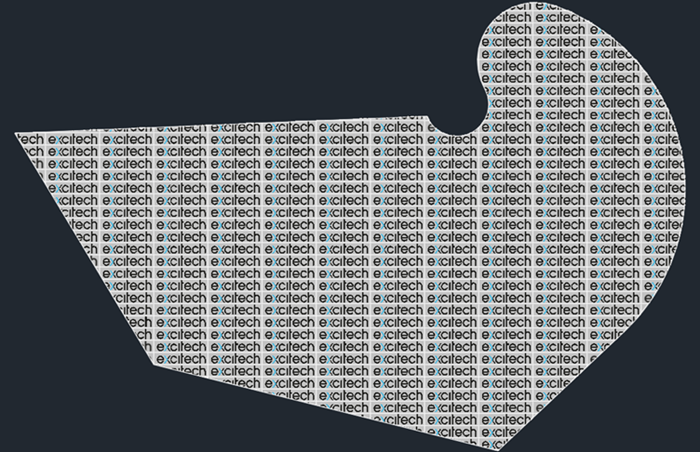
When you create a hatch in AutoCAD, you are limited to a number of patterns to choose from. While in AutoCAD you can find a wealth of patterns that come with the default installation, in some occasions you may need to apply a different one.
In this blog, we will progress step by step through an AutoCAD course exercise where we create a hatch using an image to generate the pattern.
Note: the below content was created by Excitech prior to becoming Symetri in January 2021, following its acquisition by Addnode Group. All Excitech products, services and solutions mentioned in this blog are available through Symetri.
If you are interested in further AutoCAD courses, you can have a look at our range of courses HERE.
Learn how to protect your organisation from QR code phishing, adopt passkeys securely, and manage AI note-takers with the latest IT security advice from Symetri.

Reduce downtime and improve service efficiency with AI-powered troubleshooting. Learn how service teams use ilean to solve problems faster and capture knowledge.

Cybersecurity risks are not always caused by sophisticated attacks or major system failures. In many cases, risk builds quietly through everyday habits, overlooked processes, and limited visibility into where data is stored or how users interact with systems.