
How AI Is Transforming Daily Work in Service Teams
Reduce downtime and improve service efficiency with AI-powered troubleshooting. Learn how service teams use ilean to solve problems faster and capture knowledge.
With the assistance of the Express Tools, I am going to take you through how to make two different types of Custom Linetype, sometime referred to as Complex Linetypes, within AutoCAD. The first will contain text and the second will contain a shape.

The first Linetype containing text will be called POWER and will look like this:
![]()
To begin, within an AutoCAD Drawing, set the current layer to 0.
Load the Single Line Text command and set Justification to MC (Middle Centre), Height to 1 and Rotation to 0. Type, POWER.
Now draw a Line from the Insertion Point of the Text as shown below. This is to ensure it is drawn central, vertically:

Using the Lengthen command, set the Total Length to 1. Move the line, if required, closer or further from the text then Mirror it so it appears as below:
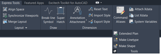
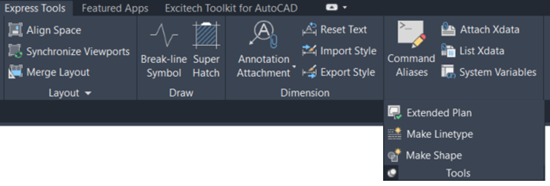
From the Express Tools Tab on the Ribbon expand the Tools Panel and select Make Linetype:
In a location of your choice create a file called My Linetypes. For Linetype Name, type POWER and
for Linetype Description, type: The word POWER within a line.
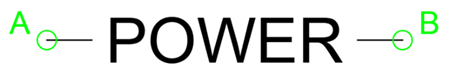
When asked to specify starting point for line definition, pick at point A and for ending point pick B as shown below:
At the Select Objects prompt select both lines and text.
After pressing Enter / Return, the command line should say the following:
Linetype "POWER" created and loaded.
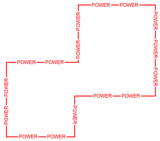
To demonstrate this has worked, create a new layer and assign the POWER Linetype. Draw a Line. If all has gone to plan you should see something like this.
Note: When AutoCAD is installed, it should load the Express Tools by default. If for any reason these are not visible within the Ribbon, type EXPRESSTOOLS, and they should appear.
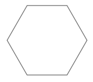
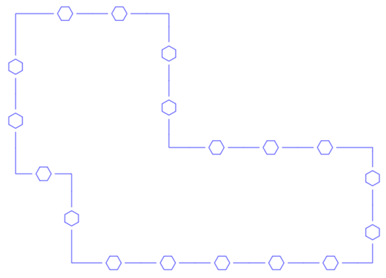
The second Linetype containing a shape is a little more involved and has an essential step at the end. It will be called, HEXAGON and will look like this:
![]()
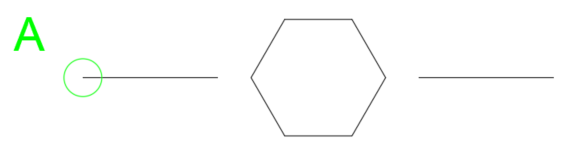
To begin, within an AutoCAD drawing, set the current layer to 0. Using the Polygon command draw the following shape. 6 Sides Inscribed and a Radius .5.
Draw lines either side, 1 long.
From the Express Tools Tab on the Ribbon expand the Tools Panel and select Make Shape.
In a location of your choice create a file called HEXAGON. For shape name type, HEX, accept default Resolution. When asked to Specify insertion base point pick at point A as shown:
At the Select Objects prompt select all objects.
After pressing Enter / Return the following message appears on the command line:
Shape "HEX" created.
Use the SHAPE command to place shapes in your drawing.
Type Shape and press Enter / Return. Enter the name of the shape which is HEX. Place the `Insertion point’ in the same location as the Insertion Base Point (A) you previously specified so the shape overlays the original drawn objects. Specify a height of 1 and a rotation angle of 0.
The reason for overlaying in this way is because when we make the Linetype we need to object snap to the ends of both horizontal lines. We cannot object Snap to a Shape other than its insertion point.
Within the Express Tools Tab on the Ribbon expand the Tools Panel and select Make Linetype.
From the same location you created the `My Linetypes.lin’ file select this file and choose Save. Say Yes to replace it. For Linetype name, type HEXAGON. For Linetype Description, type Hexagon shape within a line.
Note: The procedure above doesn’t actually replace the `My Linetypes.lin’ file at all. It simply combines the Linetypes, POWER and HEXAGON into the same file. This you will discover later.
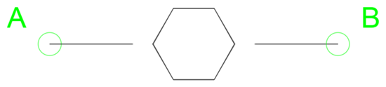
When asked to Specify starting point for line definition pick at point A and for ending point pick B as shown below:
At the Select objects prompt, select the Shape only. (NOT THE LINES UNDERNEATH)
After pressing Enter / Return, the command line should say the following:
Linetype "HEXAGON" created and loaded. To demonstrate this has worked, create a new layer and assign the HEXAGON Linetype. Draw a Line. If all has gone to plan you should see something like this.
This procedure would typically be carried out within a Template File to remove the need to do this in every new drawing.
Type COMPILE and within dialog Box select the name of the Shape (.SHP) file. HEXAGON.SHP
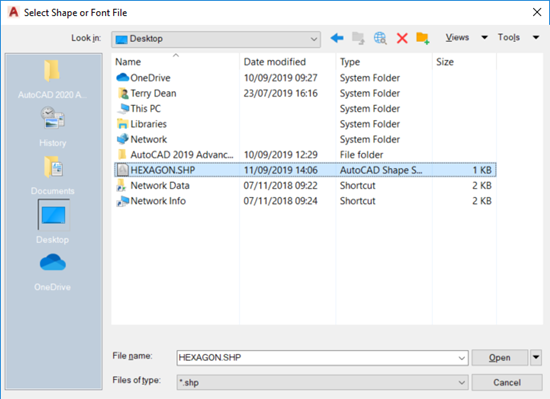
After select Open the following similar message should appear within the command line:
Compiling shape/font description file
Compilation successful. Output file C:\Users\TerryD\Desktop\HEXAGON.shx contains 115 bytes.
As you will see it has created, HEXAGON.SHX file.
Type LOAD and within Dialog Box select HEXAGON.SHX file from the location referred to in previous message.
Now type SHAPE. At Enter Shape name, type HEX then pick somewhere in drawing to place it and specify height = 1 and rotation angle = 0. You can delete this after insertion.
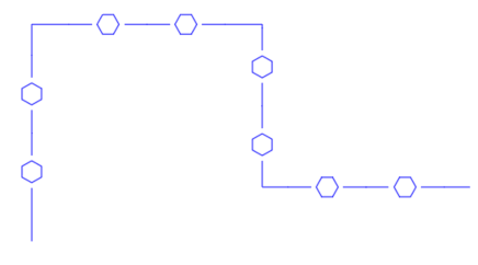
To demonstrate this has worked, create a new layer and load the HEXAGON Linetype from the file called, My Linetypes, we created earlier, and then assign to the layer HEXAGON.
Draw a Line. If all has gone to plan you should see something like this.
Well that’s it. Hope you’re successful in carrying out the steps above and it proves useful.
If you would like more information on the AutoCAD software, feel free to get in touch with us.
Reduce downtime and improve service efficiency with AI-powered troubleshooting. Learn how service teams use ilean to solve problems faster and capture knowledge.

Cybersecurity risks are not always caused by sophisticated attacks or major system failures. In many cases, risk builds quietly through everyday habits, overlooked processes, and limited visibility into where data is stored or how users interact with systems.

Learn how to reduce cyber risk through stronger security foundations. This month's bulletin covers home office security, legacy technology risks, vulnerability management, MFA, and cybersecurity best practices.