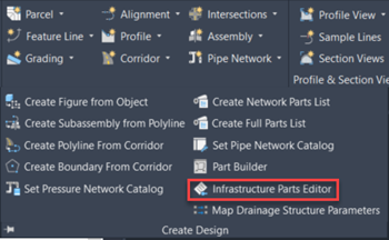
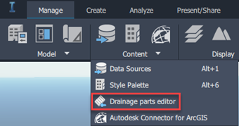
Infrastructure Parts Editor is a standalone application that can be accessed from Civil 3D (Ribbon -> Home tab -> Create Design Extended Panel) or Infraworks (Ribbon -> Manage Tab -> Content Extended Panel).
From the ‘Open my parts Lib’ menu on the left panel we can access the out-of-the-box catalogues for pipes and structures. The ‘Piping’ catalogue can be used for pressure pipes only, custom gravity pipes will still need to be created with Parts Builder.
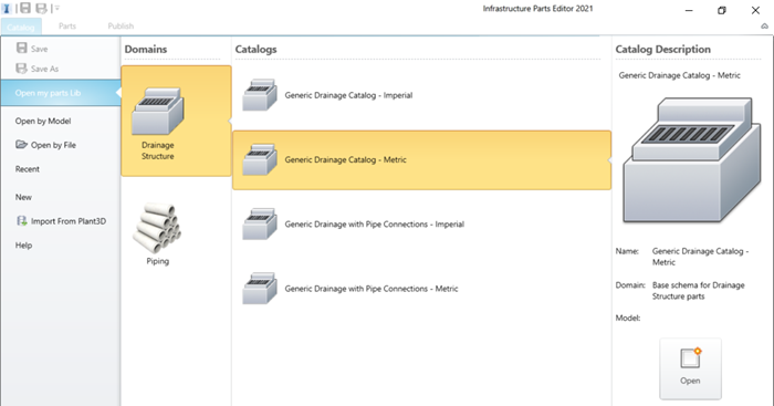
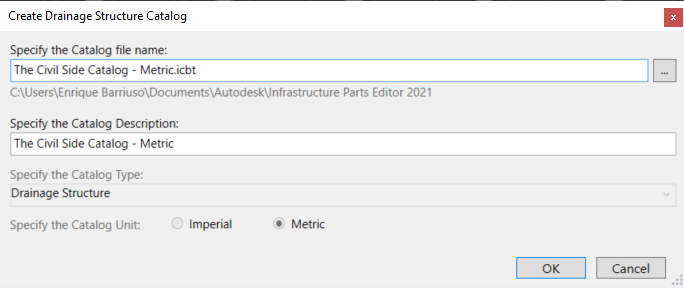
Let us start by opening the ‘Generic Drainage Catalog – Metric’. Before making any modifications, creating a copy of it using the ‘Save as’ button from the Quick Access bar and save the catalogue with a suitable name.
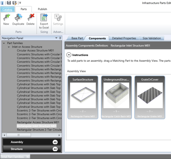
In the navigation panel, we can find a number of assemblies and structures. You may also have culverts in your catalogue. The assemblies represent the finished full part that will be published to Infraworks or Civil 3D, and they are built by joining some structures together. An inlet or access structure will combine a surface structure, an underground structure and a grate or cover. In this example, we will be modifying the underground structure of the ‘Rectangular Inlet Structure M01’ assembly.
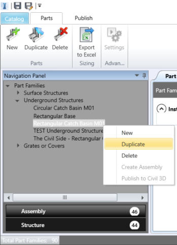
From the ‘Structure’ section, duplicate the ‘Rectangular Inlet Structure M01’.
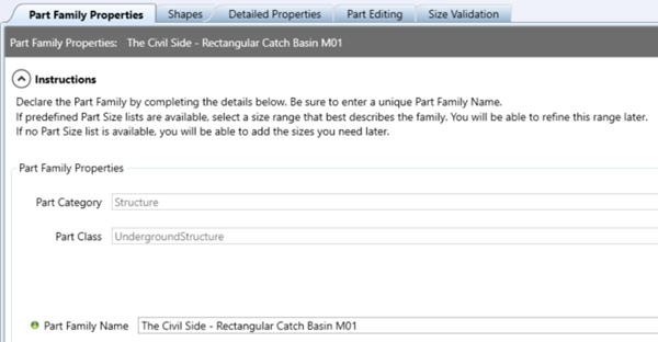
You can then rename the copy in the ‘Part Family Properties’ tab.
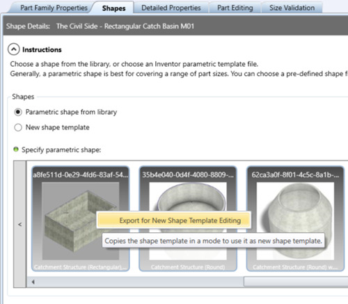
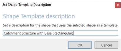
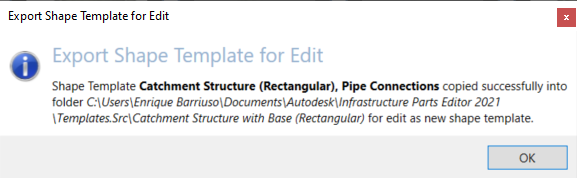
Change to the ‘Shapes’ tab, right click on the parametric shape that is selected and pick ‘Export for new Shape Template Editing’.
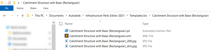
A folder will be created containing the Inventor Part File that was used to create this structure.
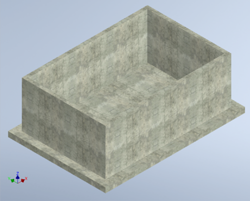
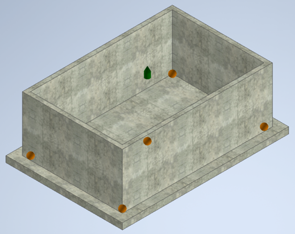
The ipt file from the previous step can be opened and modified in Inventor. Using Inventor tools, we add a base to the structure. Note how the Z axis points vertically up. You need to be aware of this if you are creating a new part from scratch, as the orientation of the Standard Inventor template is different, with the Y axis pointing up.
Some additional steps are needed before publishing the structure to Infrastructure Parts Editor. You will need to install the ‘Inventor Infrastructure Modeler Plugin 2021’ to access this functionality. You can find the installer in your Autodesk Account or Autodesk Desktop App.
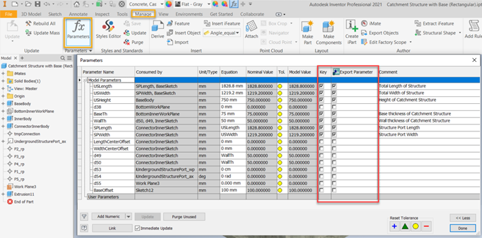
Check the ‘Key’ and the ‘Export Parameter’ columns for all the parameters that you want to make accessible from Infrastructure Parts Editor. You can expose as many parameters as you like, but some of them are required. The name and descriptions of those parameters can be found in this help FILE:
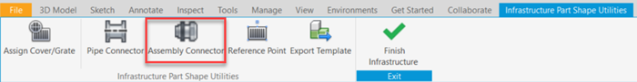
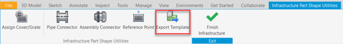
From the ‘Environments’ tab of the Ribbon in Inventor, access ‘Infrastructure Part Shape Utilities’.

An Assembly Connector (green arrow) needs to be added to the part to indicate the connection point between the underground structure and the surface structure. Because we are modifying an existing part, there is already one. Optionally, you can also create Reference Points, that determine the location of the grips in Infraworks and Civil 3D.
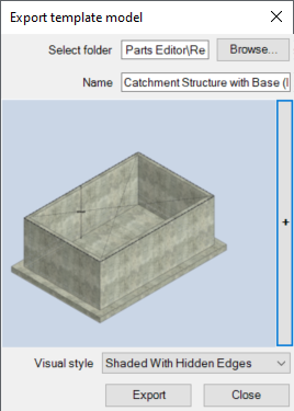
The final step in Inventor is to export the template. Pick a folder and a name to save the template. The thumbnail of the structure will also be generated from the current view.
Back in Infrastructure Parts Editor, select ‘New shape template’ and browse to the template file generated in the previous step.
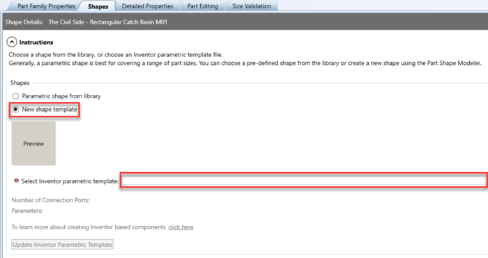
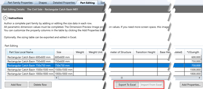
Change the ‘Detailed Properties’ section as required and add part sizes in ‘Part Editing’. All of the parameters with an asterisk are required. If adding multiple sizes, you might find useful the Export and Import to Excel buttons.
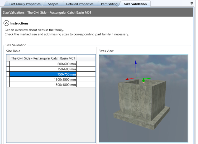
You can confirm in the ‘Size Validation’ tab that your structure is behaving as expected.
Now that the underground structure is finished, go back to the assembly that we previously duplicated and replace the underground structure with the custom one by clicking and dragging from ‘Matching Parts’ to ‘Assembly View’.
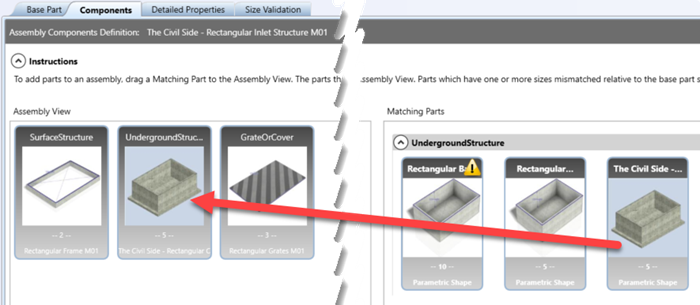
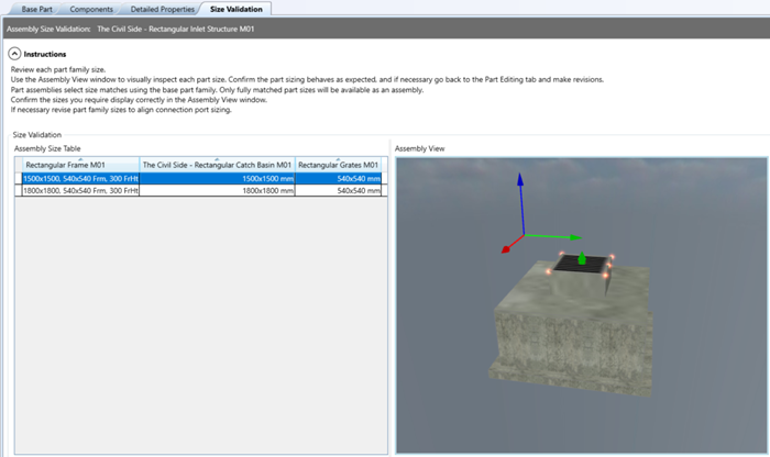
The assembly will be built by adding together matching sizes of the ‘GrateOrCover’, ‘SurfaceStructure’ and ‘UndergroundStructure’. In ‘Size Validation’, you can see a preview of the finished assembly.
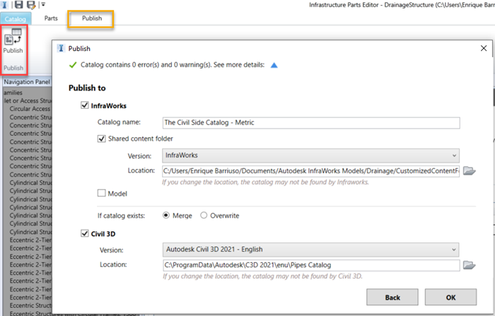
We are now ready to publish the catalogue for use in Civil 3D and Infraworks. In the case of Infraworks, you also have the option to publish the catalogue to an existing model.
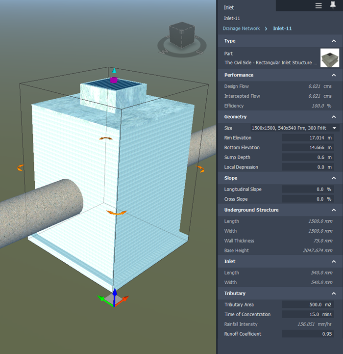
An example of the structure being used in Infraworks can be found below.
If you would like help with content creation, application automation, project support and much more, visit our website to explore our consultancy services here.
