
How AI Is Transforming Daily Work in Service Teams
Reduce downtime and improve service efficiency with AI-powered troubleshooting. Learn how service teams use ilean to solve problems faster and capture knowledge.
In this blog article, we are going to take a look at different electrical symbols and symbol types within AutoCAD Electrical.

Electrical symbols within AutoCAD Electrical consist of an attributed block with required and optional electrical attributes that defined the symbol type. A feature within AutoCAD Electrical called ‘Symbol Builder’ is used to define the symbol and component type, including the block objects and insertion point.
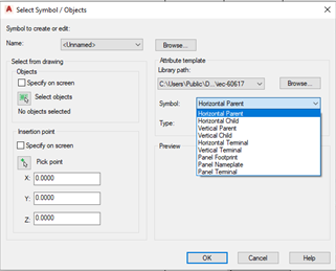
The different symbol types available are:
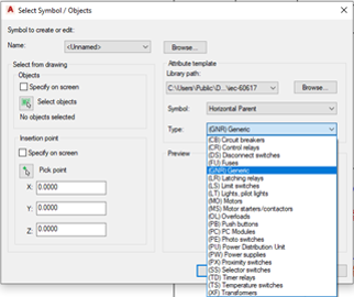
The component type list can be adjusted to include/remove specific component types by amending the attribute template files within the specified library path within ‘Symbol Builder’.
An example of an attribute template files for a circuit breaker is shown below:
AT_HP_CB
where AT = Attribute Template, HP = Horizontal Parent and CB = Circuit Breaker
AT_VP_CB
where AT = Attribute Template, HC = Vertical Parent and CB = Circuit Breaker
AT_HC_CB
where AT = Attribute Template, HC = Horizontal Child and CB = Circuit Breaker
AT_VC_CB
where AT = Attribute Template, HC = Vertical Child and CB = Circuit Breaker
Depending on what symbol type and component type is selected, this will provide the user with the specific required and optional attributes.
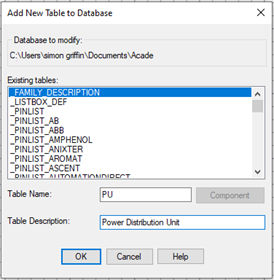
If the component type description is required for the new component i.e. (PU) Power Distribution Unit. This is achieved by adding the new table to the catalogue database (Project Tab > Other Tools drop down), select the required catalogue that is being used and within the existing table ‘_FAMILY_DESCRIPTION’, Add the table name and description as shown in the example below:
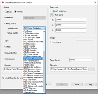
Once the attribute templates have been set up, they will also be available when saving custom symbols within the symbol builder using the file naming convention in AutoCAD Electrical as shown in the example below:

If you would like further information on the benefits of using AutoCAD Electrical for your electrical design, feel free to contact us at Symetri to arrange a consultation with one of our electrical specialists.
We offer scheduled AutoCAD Electrical essentials training, as well as bespoke training tailored to your requirements to help you work smarter for a better future.
To learn more about AutoCAD Electrical, please visit our product page or contact us by email info@symetri.co.uk or telephone 0345 370 1444.
Reduce downtime and improve service efficiency with AI-powered troubleshooting. Learn how service teams use ilean to solve problems faster and capture knowledge.

Cybersecurity risks are not always caused by sophisticated attacks or major system failures. In many cases, risk builds quietly through everyday habits, overlooked processes, and limited visibility into where data is stored or how users interact with systems.

Learn how to reduce cyber risk through stronger security foundations. This month's bulletin covers home office security, legacy technology risks, vulnerability management, MFA, and cybersecurity best practices.