
Securing the Modern Workplace
Learn how to protect your organisation from QR code phishing, adopt passkeys securely, and manage AI note-takers with the latest IT security advice from Symetri.
In this blog, we give you the top ten tips you need to utilise Inventor Nastran.
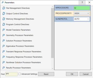
1. To enable Nastran to use all your computer’s cores for faster solution times, change the NPROCESSORS parameter value to your computer's maximum number of cores. The default value is normally 4.
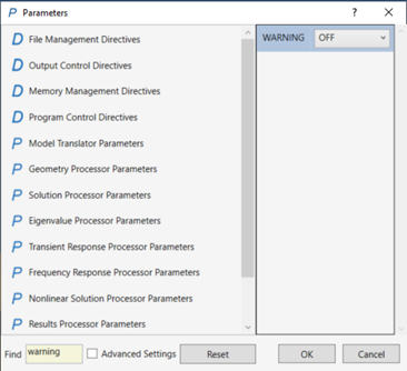
2. Typically, when you run Inventor Nastran, many warnings can appear, resulting in large output files. This can be significantly reduced by changing the WARNING parameter value to OFF.
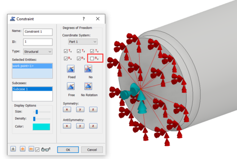
3. Solid elements do not allow rotational degrees of freedom. So, for example, if you need to simulate a simple supported shaft, you can define rigid body connectors on the desired locations and then select the point for assigning constraints. You can then release the desired rotational degree of freedom to simulate a pin connection.
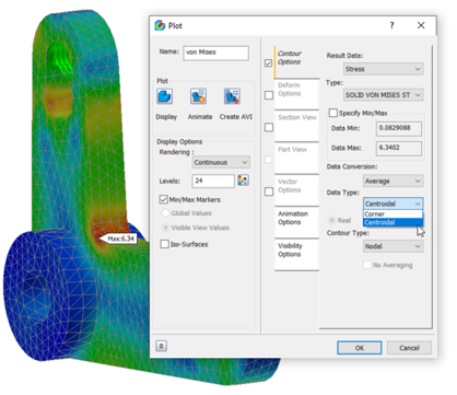
4. You can achieve mesh convergence by checking Corner and Centroidal Data Type results. If the difference in value is less than 10%, you can assume convergence has been achieved. Note the maximum value needs to be in the same place.
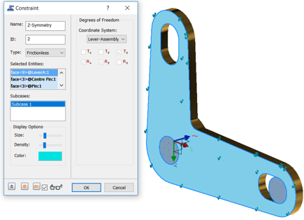
5. You can define symmetry conditions, using frictional constraints.
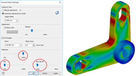
6. You can use Ground Plane settings to display half model results as full model.
7. When analysing bolted connections within Inventor Nastran you can include washers from the inventor environment. This will remove the need to define split faces required to correctly define the load-bearing faces.
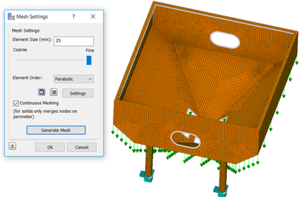
8. Use Continuous Meshing when using surface models and shell elements. This will remove the need to add contacts between individual surfaces.
9. Always use Shell elements when you have thin models with a ratio of 1:30 or above (1mm thick and 30mm long).
10. Always use Solver Offset Bonded contacts for models converted to surfaces using either Find Thin Bodies or Midsurfaces.
To learn more about Inventor Nastran, visit our extensive training courses or feel free to get in touch by filling in the form.
Learn how to protect your organisation from QR code phishing, adopt passkeys securely, and manage AI note-takers with the latest IT security advice from Symetri.

Reduce downtime and improve service efficiency with AI-powered troubleshooting. Learn how service teams use ilean to solve problems faster and capture knowledge.

Cybersecurity risks are not always caused by sophisticated attacks or major system failures. In many cases, risk builds quietly through everyday habits, overlooked processes, and limited visibility into where data is stored or how users interact with systems.