
How AI Is Transforming Daily Work in Service Teams
Reduce downtime and improve service efficiency with AI-powered troubleshooting. Learn how service teams use ilean to solve problems faster and capture knowledge.

Producing a 3D model may seem the complicated part but usually shows the functionality, and accurately showing sizes which can cause the issues. So, in this post I will go through how these commands work in Inventor Professional.
Opening and Creating Drawings
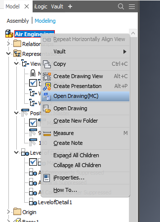
Let’s start with a tip on opening and creating drawings in Inventor Professional. You can use the file tab, but there is an easier way. When you’re in the model tree, right click on either the master .ipt or .iam file and either Create Drawing View or Open Drawing will be available. By selecting the Create Drawing View, it will allow you to choose which template you would like to use and will open up the Base View dialogue box in a new drawing. The Open Drawing will open the drawing associated to the model.
Break![]()
The break command can be very useful for lengthy objects with the same profile throughout. A great example of this is a conveyor as the profile will be consistent from end to end, with the scale being too long for the page.
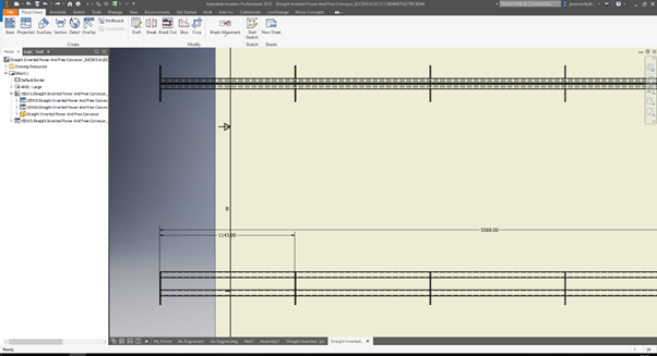
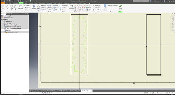
With the break command you can create a split that will show in the view of the model, and also any views projected from it. To use the command, select Break and then select the view in which you are looking to split, this dialogue box will then appear:
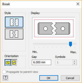
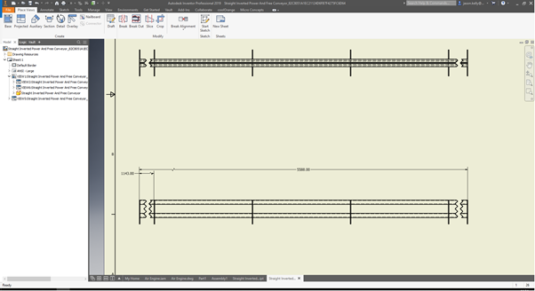
In here you can select the orientation of the break and the style of how the break will look. Just select the area you would like the break to be, ensuring the first selection will be the start of the break and the second at the end. You can also create multiple breaks on the same view, however, these will need to be separate instances of the break command. The final result is shown below:
Breakout
The breakout command is useful for showing locations of interior parts on a drawing. A good example of this is if you are looking to show the engine in a car. You could use Breakout to remove the exterior.
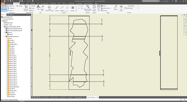
The example I am going to show is a wardrobe, with the breakout view showing the location of the shelves.
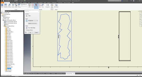
The first step is to create a sketch on the view. As normal, go to the Sketch tab and ‘start sketch’ on the view you are looking to create the breakout. The sketch created can be any shape as shown by the extreme example below, but has to be closed.
Finish the sketch and go back to the Place Views ribbon.
Select Breakout and then the view you have created the sketch on. This should automatically select the sketch. If it doesn’t select the cursor next to Profile, then select the sketch yourself. Next, select the drop down in Depth - in here you will notice there are a few options, however for this example (and in most cases) I am going to use the Through Part command. This will put the ‘cut’ through the selected part. You can then select the part from the browser tree, or by just selecting on an edge.
Once all parts are selected, click OK and it will then create your breakout.
Slice![]()
The slice command will view cross section cuts of a model. This can be useful for longer parts with varying profiles as it displays the cross section of a line passing through the model on to a projected 2d or 3d view. The process is very similar to that of a breakout. Create the sketch onto the view (not the view you are wishing to slice), making sure that this time the sketch is not closed. If the lines cross through a part, the profile will be selected (as shown below). For this example, I have lofted 4 different shapes and will expose them using the slice command.
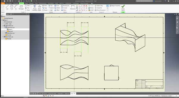
To create the slice, you will first need to select the Slice tool, then the view you wish to create the slice in (in this example the 3D view). A dialogue box will then appear for you to select the sketch and check the box, whether you are wanting to include the whole part or an assembly of all parts. Then click OK.
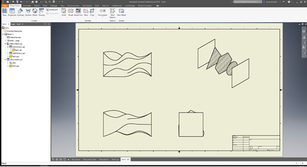
The slice will then be created for you. The sketch lines do not need to be at a 90-degree angle, it will bring through the profile from the two widest parts of the line.
Crop![]()
The Crop tool in Inventor Professional is very similar to other crop tools used in photo editing software. Once activated, pick on the view that you are wishing to crop, and then using the rectangle tool to draw around the point you wish to crop. This tool can be useful for highlighting key points in assemblies.
Align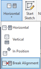
The align commands are a quick way of correcting your Inventor drawings to either make sure all projected views are aligned correctly or to break alignments to create space on the page. To use these commands first pick an alignment (for this example I am going to use horizontal). Then simply select both of the views and they will snap together forming a link. If one view doesn’t move, the other view will follow the same path. To break the alignment simply select the Break Alignment and then the projected view you wish to break. This will then name the projected view and show the location (the same as a projected view).
Take a look at our wide range of Inventor Professional training courses and gain access to our experienced trainers and more of their tips.
Reduce downtime and improve service efficiency with AI-powered troubleshooting. Learn how service teams use ilean to solve problems faster and capture knowledge.

Cybersecurity risks are not always caused by sophisticated attacks or major system failures. In many cases, risk builds quietly through everyday habits, overlooked processes, and limited visibility into where data is stored or how users interact with systems.

Learn how to reduce cyber risk through stronger security foundations. This month's bulletin covers home office security, legacy technology risks, vulnerability management, MFA, and cybersecurity best practices.