What’s New in Inventor 2027: A Guide to the Latest Features
Consultant Jason Kelly explores the new 2027 features in Autodesk Inventor Professional. Including updates to the content center and Autodesk Assistant
In the following post we will be modelling a spring in SketchUp. Although there are some extensions that will speed up the process, the method shown here will only use tools that are native to SketchUp.
The spring will have a mean diameter of 100 mm, a wire diameter of 10 mm, and 5 turns with a pitch of 50 mm, as shown below.

We start by drawing a circle with a 50 mm radius centred in the origin. Select the circumference of the circle and expand ‘Entity Info’ in the ‘Default tray’ to verify the number of segments that make up the circle. The default value is 24, which means that the circle is modelled in SketchUp as a polygon with 24 sides. We will employ this fact in the following steps to create the helix that will be used as the path for the spring.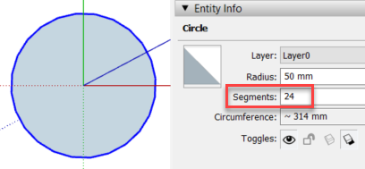
With the circle still selected, right click on it and pick ‘Explode Curve’. This will convert the circumference into 24 separate lines.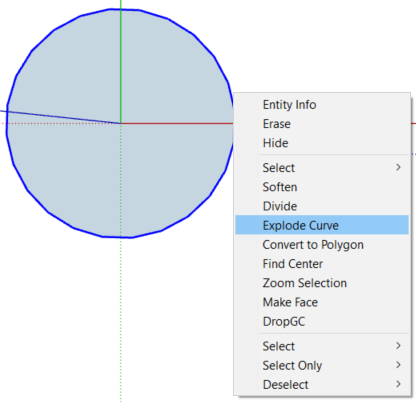
Delete everything except one of the lines and move one of the vertices of the line up in the blue direction by an arbitrary distance. The pitch of the spring will be adjusted later on.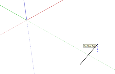
Select the line, launch the rotate command, and create 24 copies of it rotating it around the origin. The prompts in the status bar (bottom left) will guide you through the sequence of steps. You can press <Control> once to keep the original line and then type ‘x23’ after the first copy is placed to create a polar array with 23 additional lines, 24 in total.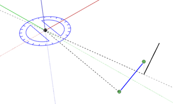

Select all the lines and, using the move command, copy them directly on top and use the ‘x23’ option again to stack 24 copies vertically.
At this point we have 24 helixes of exactly 1 turn. Select one of them by triple clicking on it and invert the selection from the right click menu to select the remaining 23. Press the delete key to only leave one helix.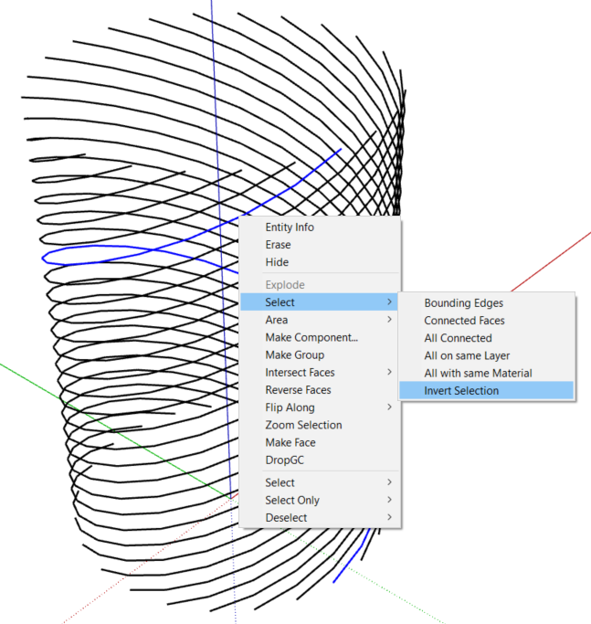
With the ‘Tape Measure’ tool, create a guide point on the blue axis 50 mm up from the origin.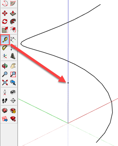
Select the helix and use the ‘Scale’ tool to adjust the height to the guide point. You will need to drag the grip on the middle of the top face in order to scale only in the blue direction. You can then pick ‘Delete Guides’ from the ‘Edit’ menu to delete the guide point.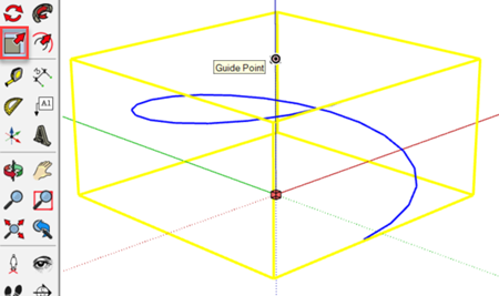
Stack an additional 4 copies of the helix to end up with a total of five turns.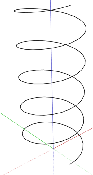
Select the helix and right click on it to make it a component.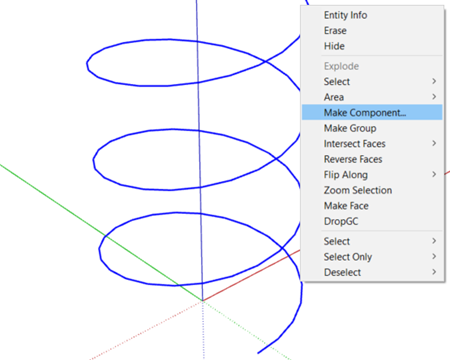
In the ‘Create Component’ dialog, use the ‘Set Component Axes’ button to orient the local red axis of the component in the direction of the line. This will facilitate drawing the circle that represents the cross section of the spring in a plane perpendicular to the helix.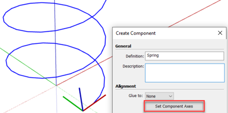
Get inside the component and draw a circle in the red plane, perpendicular to the red axis, with a radius of 5 mm.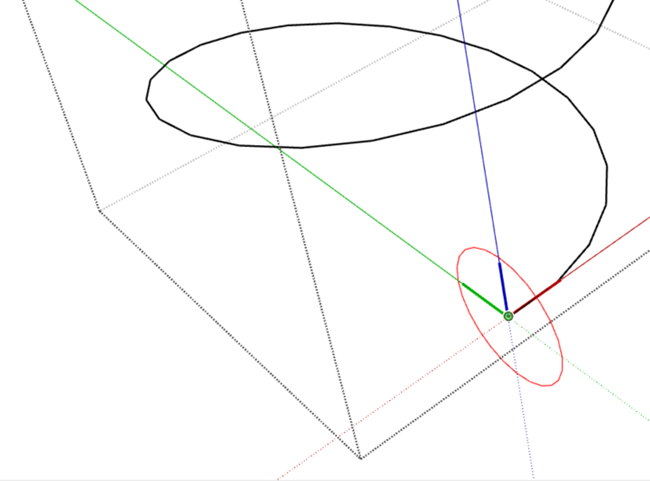
Select the helix, launch the ‘Follow me’ tool, and finally select the circle to extrude it along the path.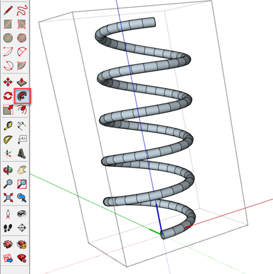
To avoid the segmentation, select the spring and check the ‘Smooth normals’ option from the ‘Soften Edges’ section of the ‘Default Tray’. If it is already checked, uncheck it and check it again.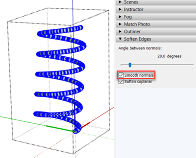
Apply a material to the spring, exit the component and right click on it to change the component axes to match the global axes. This change will ensure that new instances of the spring component will be inserted centred and in a vertical position.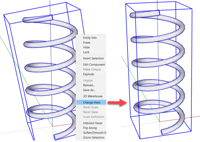
If you would like to expand your SketchUp skills, explore our SketchUp training courses HERE.
Consultant Jason Kelly explores the new 2027 features in Autodesk Inventor Professional. Including updates to the content center and Autodesk Assistant
Vault 2027 release includes improved property handling, stronger PLM connectivity, and the introduction of the AI‑powered assistant.
AutoCAD 2027 introduces new tools to improve collaboration, drawing accuracy, and productivity, including Autodesk Forma data management integration, Geometry Cleanup, and the AI‑powered Autodesk Assistant. In this guide, we highlight the key AutoCAD 2027 updates and explain how they support more efficient, connected workflows for design teams.