
How AI Is Transforming Daily Work in Service Teams
Reduce downtime and improve service efficiency with AI-powered troubleshooting. Learn how service teams use ilean to solve problems faster and capture knowledge.
Simulation has come a long way from the days when it was used by a few select experts. Today the technology, like Autodesk Nastran In-CAD, has become more accessible and easier to use. This in turn makes it easier for designers and engineers like you to adopt simulation early on within the design process as this is where it has the most impact. Despite the simulation technology becoming easier to use there remains one fundamental question on the mind of every designer and engineer: How do I know my results are correct?
Nastran In-CAD, although easy to use, has a comprehensive set of tools to help you answer this question and make sense of your results. These include mesh convergence, nodal and elemental result plots, section views, and much more including workflows and tips based on industry best practices.
Over the coming weeks I will be sharing some of my experiences in the hope to make you more comfortable in using Autodesk Nastran In-CAD to help you make innovative products.
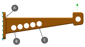
Today I would like to highlight that all engineers designing products typically have a very good idea of where they expect their design to experience high stresses without using any commercial simulation package. So, let’s take the following simple example where would you expect the highest stress to be?
The answer is B. As the model gets more complex it becomes extremely difficult and tedious to determine the stress and safety factors of your design with just hand calculations. This is where simulation can help and provide more insight into the model in addition to being able to calculate stress results. This then leads to my next section on how do I know my stress results are correct (or converged-meaning will not change if I change the mesh).
Continue with the next blog in this series 'Simulation for designers - Results convergence'
Reduce downtime and improve service efficiency with AI-powered troubleshooting. Learn how service teams use ilean to solve problems faster and capture knowledge.

Cybersecurity risks are not always caused by sophisticated attacks or major system failures. In many cases, risk builds quietly through everyday habits, overlooked processes, and limited visibility into where data is stored or how users interact with systems.

Learn how to reduce cyber risk through stronger security foundations. This month's bulletin covers home office security, legacy technology risks, vulnerability management, MFA, and cybersecurity best practices.