Simulation for Designers - Fringe Display Stress Plots

As mentioned in the previous article, based on best practice, there is a need to analyse results at least three times, to check whether the stress results have converged. In most cases, hopefully, the difference in stress values will become minimal. But however, due to stress singularities, the stress values will not converge.

FIND OUT MORE INFORMATION ABOUT SIMULATION Read our blogs and case studies, or watch our short videos and on-demand webinars. FIND OUT MORE

In these scenarios, Nastran In-CAD's comprehensive set of post-processing tools can prove to be helpful. Since there are many post-processing tools available within Nastran In-CAD here will initially discuss Fringe Display plots.

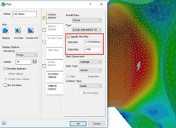
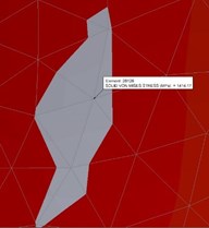
The main benefit of using fringe results is that once we alter the maximum value of the legend bar any value higher than the new maximum will be displayed as grey. This can prove to be very useful as we can use this technique to isolate high stresses due to singularities and concentrate on the area of interest.


It is important to note that altering the maximum value is not about fiddling (non-technical term) with results but is merely about presenting results which are meaningful. Once we have a minimal grey area we can use the probe tool available within Nastran In-CAD to display the maximum value. The benefit of using a fringe display and probes like this is to help locate the maximum value location with ease in the area of interest within the model.

I hope you find this tool helpful, and continue with the next blog in this series 'Exploring corner stress plots'


Security Gaps You Didn't Know You Had

26 August 2025

As cybersecurity threats continue to evolve, some of the biggest risks to your organisation might not be obvious. In this month’s IT Bulletin, we shine a light on three critical security concerns that are often underestimated or overlooked entirely. These issues can silently compromise systems, leak data, or be exploited without detection.

What's New in Factory 2026

14 August 2025

The latest updates to Factory Design 2026 bring powerful improvements to connector class creation, workflow efficiency, and overall performance. From a brand-new Connector Class dialogue to enhanced 4K compatibility and stability upgrades, these changes are designed to make your design process faster, smoother, and more intuitive.

CAD and PLM: Why It’s the Solution for Manufacturing and Engineering Companies

29 July 2025

Efficiency, accuracy, and innovation are crucial for staying competitive in the industrial landscape of today. Manufacturing and engineering companies face increasing challenges in managing product development, ensuring design accuracy, and optimising workflows. That’s where Computer-Aided Design (CAD) and Product Lifecycle Management (PLM) come into play.