
Securing the Modern Workplace
Learn how to protect your organisation from QR code phishing, adopt passkeys securely, and manage AI note-takers with the latest IT security advice from Symetri.
Never rely on one set of Analysis Results. The only exception to this is displacement results. However, in most cases, we are usually interested in stress results which are required to calculate the factor of safety of our designs. When analysing results, we need to make sure the stress value is not affected by changing the mesh size.
I usually get asked a lot "What element size should I use to get an accurate result?" In response to the question I usually say, "I honestly don't know" but I also say, "Analyse your results 3 times with a different mesh size in each analysis". This is more formally known as manual mesh convergence (sometimes also referred to as mesh sensitivity study).
Below is my suggested workflow*.
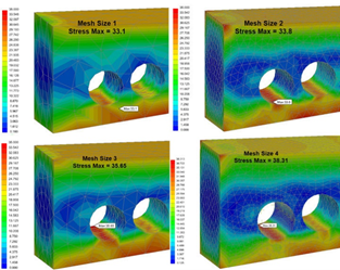
Step 1 - Analyse with default mesh size.
Step 2 - Analyse again by reducing the mesh element size by half.
Step 3 - Analyse again by further reducing the Step 2 mesh size by half.
Sometimes you may need to run an analysis a fourth time in the case when stress comparison is either very close to 10% or above it. If this is the case I suggest you use local mesh control at the area of high interest rather than changing the global mesh size. This will help to reduce the file size in addition to quicker run times.
However, in some cases, the stress value will keep on rising as you make the mesh finer. This phenomenon is referred to as stress singularities (or hotspots) which leads to my next section on stress singularities and how to avoid them.
If you have found this blog to be useful, read the next blog in this series 'What is stress singularity and why does it occur in design and models'
* Some software's have the ability to run a mesh sensitivity study.
Learn how to protect your organisation from QR code phishing, adopt passkeys securely, and manage AI note-takers with the latest IT security advice from Symetri.

Reduce downtime and improve service efficiency with AI-powered troubleshooting. Learn how service teams use ilean to solve problems faster and capture knowledge.

Cybersecurity risks are not always caused by sophisticated attacks or major system failures. In many cases, risk builds quietly through everyday habits, overlooked processes, and limited visibility into where data is stored or how users interact with systems.