
Securing the Modern Workplace
Learn how to protect your organisation from QR code phishing, adopt passkeys securely, and manage AI note-takers with the latest IT security advice from Symetri.
Stress singularities are a major headache when analysing results as they considerably distort results! They are also a main cause for the non-convergence of results. This can further lead to a lack of confidence in results and in extreme cases not using simulation at all.
So, what is stress singularity and why does it occur even in the simplest of designs and models?
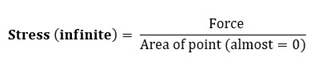
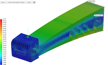
This can be best explained by the above simple bracket example which shows a high localised stress around the force applied on a point. This stress can be considerably higher than the operational stress and applying a denser mesh around this simply leads to a much higher stress. This phenomenon is known as stress singularity where the stress can become infinite, as illustrated by the following formula;
Therefore, to avoid stress singularities when applying loads, it is recommended not to apply loads at points and small edges. Stress Singularities can also occur by applying constraints on points and small edges – even faces with sharp corners as illustrated here.
Finally, another cause of stress singularity is the over-simplification of components as illustrated below.
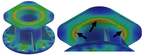
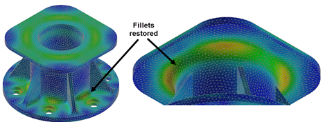
In this example, the fillets have been removed to simplify the analysis; however, when we keep refining the mesh, the maximum stress value does not converge as all the stress is concentrated around the edge, as shown above. In this scenario, it would be advisable to un-suppress the fillets to help distribute the load more uniformly as shown below.
Over time and with experience it will become easier and easier to interrogate the results of models and designs with stress singularities present.
Nastran In-CAD provides a comprehensive set of post-processing results that can help you gain more confidence when analysing results.
I hope you have enjoyed this blog. This next blog in this series will cover Fringe Display Stress Plots.
Learn how to protect your organisation from QR code phishing, adopt passkeys securely, and manage AI note-takers with the latest IT security advice from Symetri.

Reduce downtime and improve service efficiency with AI-powered troubleshooting. Learn how service teams use ilean to solve problems faster and capture knowledge.

Cybersecurity risks are not always caused by sophisticated attacks or major system failures. In many cases, risk builds quietly through everyday habits, overlooked processes, and limited visibility into where data is stored or how users interact with systems.