Microdrainage, with its 35 years of innovation, has successfully enabled water professionals worldwide to create precise and effective designs and models for surface water and wastewater systems. Drawing from this extensive experience, Autodesk developed InfoDrainage, a cutting-edge drainage design application launched in 2020. InfoDrainage was specifically designed to meet the growing requirements for sustainability, compliance, and efficient approvals. Read this blog to discover 10 improvements you may not have known about how InfoDrainage has radically improved on Microdrainage:
- More accurate representation of SuDS
- You can reconnect sub-catchments
- Civil 3D integration (roundtripping)
- Flexibility for international projects
- Bifurcation and complex drainage arrangement
- SuDS inlet and outlet structures
- Phase management tools
- Model rainwater harvesting tanks
- Validation *before* your analysis
- Object and project templates
1. More accurate representation of SuDS
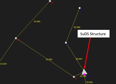
In Microdrainage, SuDS structures are represented as a storage node with no dimensions. This means that while the SuDS volume is shown, the time of concentration of water flowing through various SuDS structures is not.
More data, more detail, more insight
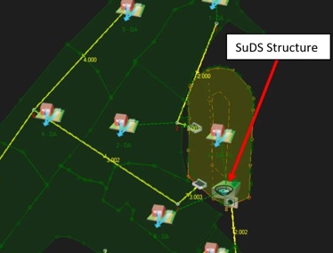
In InfoDrainage, the physical dimensions of SuDS structures are accurately spatially represented using advanced parameters. These parameters allow for modelling the depth, porosity, and hydraulic conductivity of different filtration layers that may exist beneath a SuDS structure. If there is a need to depict gravel and sand layers beneath bioretention features, InfoDrainage excels in providing significantly enhanced accuracy.
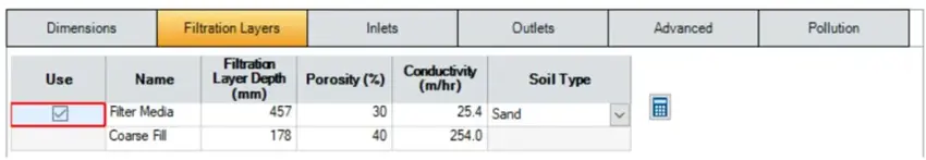
SuDS parameterisation in InfoDrainage
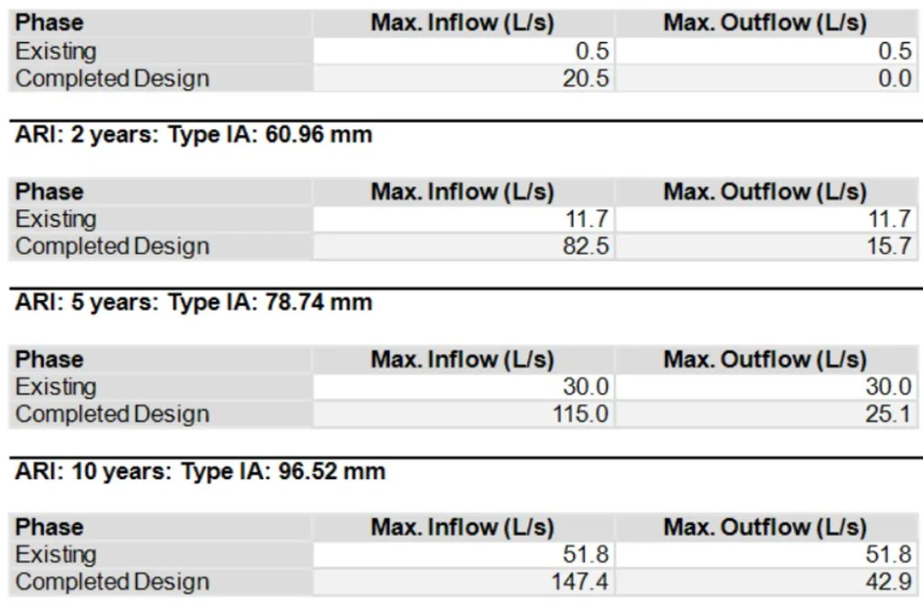
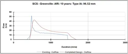
InfoDrainage's advanced physical representation enables it to accurately capture the hydraulic performance of SuDS structures. This capability is demonstrated by benchmarking results from a project involving Claylands Pond in Scotland. The results showcase the monitoring of the inlet and outlet chambers of the pond during various rainfall events as part of the Scottish SuDS Monitoring Programme.
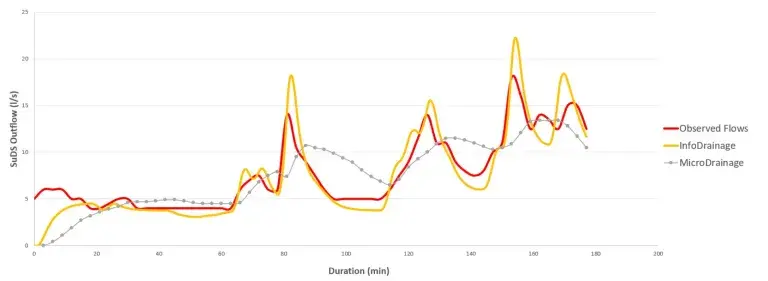
Benchmarking results for Claylands Pond in Scotland.
To replicate a storm event and compare the simulated outflow from both MicroDrainage and InfoDrainage against the observed monitored outflows (real-time data), they utilised the observed inflow and injected the inflows as an input hydrograph at the upstream end of the Claytons Pond model.
Upon analysing the results, it is evident that InfoDrainage provides a closer match to the observed flows.
2. You can reconnect sub-catchments
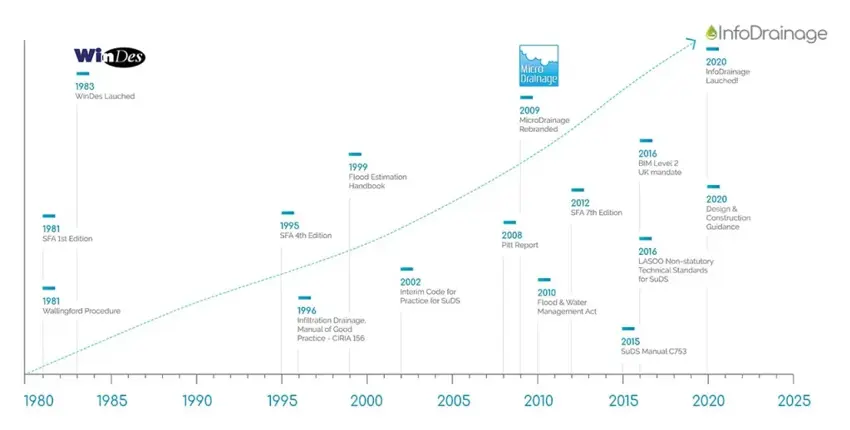
The evolution from MicroDrainage to InfoDrainage – 35+ years!
In the early 2000s, MicroDrainage added digitised sub-catchments, and experienced water professionals may recall the time-consuming task of deleting and redrawing sub-catchments whenever design revisions were necessary. In essence, MicroDrainage does not provide the capability to redirect the same sub-catchment.
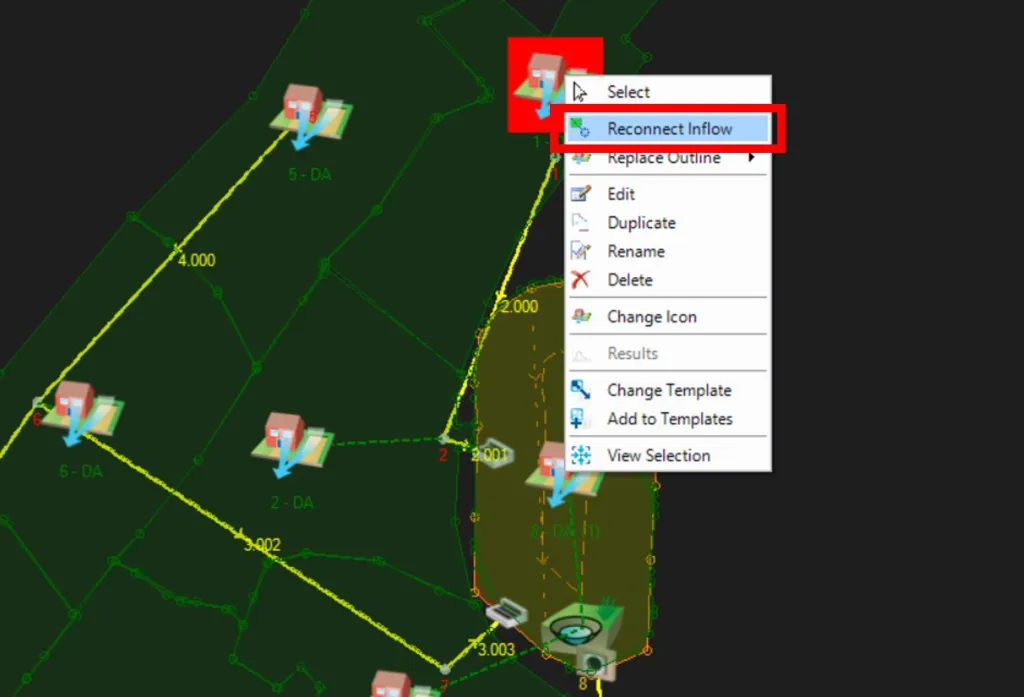
You don’t have to redraw sub-catchments in Infodrainage.
Now, not only can you easily reconnect sub-catchments when revising the drainage design, but you can also import GIS or CAD polygons. These imported polygons are automatically recognised as sub-catchments and seamlessly connected to nodes within their boundaries. This streamlined process saves time and enhances efficiency in drainage design workflows.
3. Civil 3D integration (roundtripping)
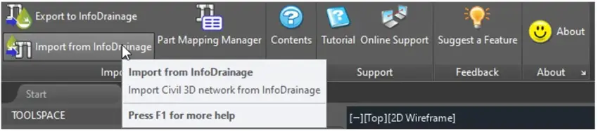
Some water professionals utilise the DrawNet(CAD) module in Autodesk Civil 3D to create MicroDrainage models based on any Civil 3D network using the Parts Mapping Manager. In MicroDrainage, the DrawNet(CAD) functionality allows for exporting and importing pipes, manholes, open-sections, and surfaces directly into Civil 3D, as these elements are represented by smart Civil 3D objects. However, if modifications are made to the network elements within Civil 3D due to clash detection or site constraints identified in Civil 3D or Navisworks, the drainage network must be simulated again. In such cases, the rainfall data, sub-catchments, and runoff coefficients must be redefined in MicroDrainage to conduct further analysis on the revised network.
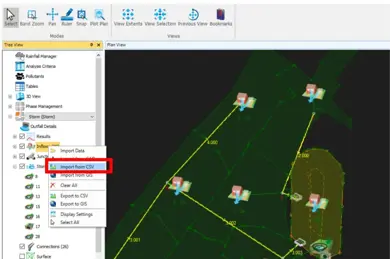
Do you use Civil 3D? You can import sub-catchments directly from InfoDrainage.
This has been improved in InfoDrainage. When exporting the drainage model to Civil 3D, all the associated data related to the model, such as rainfall, sub-catchments, and runoff coefficients, are preserved. This ensures that when the model is brought back to InfoDrainage, all the sub-catchment connections and associated runoff coefficients are ready for simulation. This seamless roundtrip between InfoDrainage and Civil 3D can be repeated as needed to ensure that the design not only complies with statutory regulations but also integrates smoothly within the Civil 3D model.
4. Flexibility for international projects
Originally designed for the UK market, MicroDrainage included features to generate rainfall based on IDF (Intensity-Duration-Frequency) curves, enabling work on international projects. However, InfoDrainage takes it a step further by incorporating design rainfall, peak flow calculation, and runoff methods directly within the software. This enhancement allows InfoDrainage to support drainage design not only in the UK but also in various countries including France, USA, Germany, Spain, Middle East, China, Japan, and Australia.
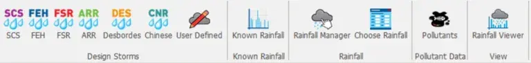
Should you use FSR or FEH? You have lots of international options in InfoDrainage.
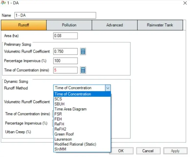
Just choose your preferred runoff equation from the drop-down menu.
5. Bifurcation and complex drainage arrangement
In MicroDrainage, modelling bifurcation is not possible due to the numbering system adopted: dendritic numbering. As a result, the industry had to resort to offline loops for volumetric exchange among multiple outgoing branches. However, the presence of multiple offline loops in a model is often associated with decreased accuracy and model instability, necessitating the use of reduced timesteps when running the hydraulic model.
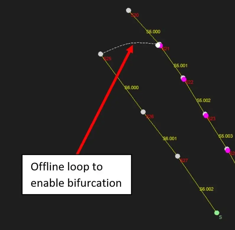
Including multiple offline loops in Microdrainage often resulted in reduced accuracy and instability.
With InfoDrainage, you have the capability to model any number of bifurcations necessary to accurately represent the physical drainage arrangement. This empowers you to confidently design complex drainage systems with precision and accuracy.
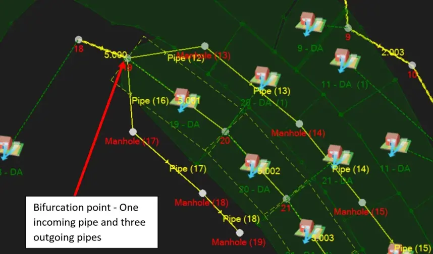
With InfoDrainage, bifurcation is simply not a problem anymore.
6. SuDS inlet and outlet structures
In MicroDrainage, SuDS inlets are visualised using pipes that discharge into the centre of a SuDS node, while outlets are represented by a single outgoing pipe from the centre of the node. This approach can lead to inaccuracies in cost estimation during material take-off, as certain pipes may be missing – as well as additional dummy pipes created – to enable the representation of complex drainage arrangements. Over time, it became evident that this workflow could result in construction issues or conflicts with existing utilities. This is primarily due to information gaps that occur when exporting drawings from MicroDrainage into AutoCAD, especially when hydraulic modelling and drainage design drawings are handled by separate teams.
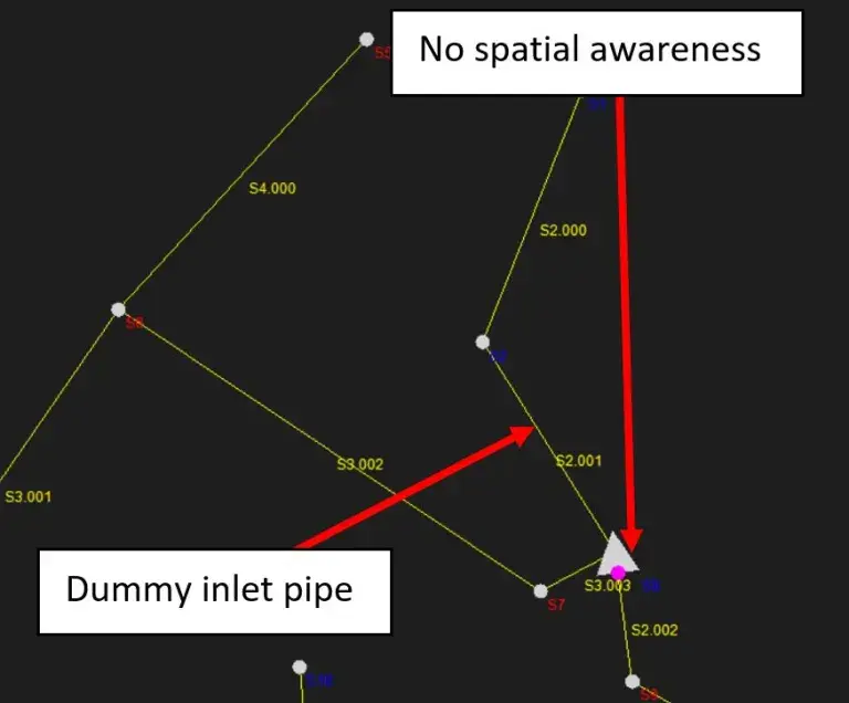
MicroDrainage didn’t provide accurate cost estimates because of dummy pipes – or missing pipes.
InfoDrainage was developed to provide designers with spatial awareness of SuDS structures, inlet pipes, and outlet structures. This enables a more precise clash detection analysis against site constraints such as existing fences, utilities, and trees. By identifying potential clashes early within the hydraulic model, designers can accurately size their SuDS structures.
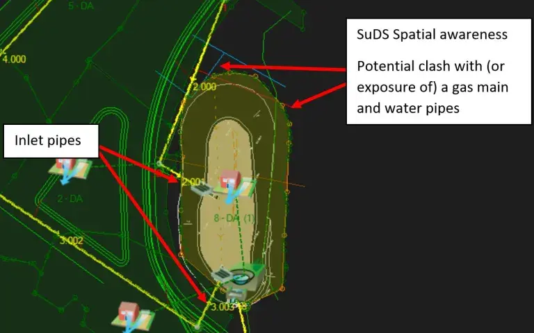
It’s much easier to spot potential clashes early in your model build in InfoDrainage.
7. Phase management tools
An effective drainage design involves conducting an optioneering exercise with multiple iterations to explore all possibilities and determine the optimal location, volume, and type of storage structures that yield the best results at the lowest cost.
In MicroDrainage, this optioneering process involved creating numerous drainage models/files, running simulations, exporting results, comparing them in Excel or other data analysis tools, and generating a report based on the comparison outcomes. Unfortunately, this approach proved to be extremely time-consuming and sometimes financially burdensome. The associated time penalty often discouraged drainage designers from iterating on the design or conducting comprehensive optioneering exercises for each project.
Compare multiple scenarios as a table or as a graph.
InfoDrainage incorporates a valuable tool called Phase Management, enabling the creation of multiple scenarios for analysis and generating comprehensive reports that compare all the scenarios. This tool significantly reduces the manual effort required to prepare comparison reports, saving over 90% of the time typically spent on such tasks. Moreover, having the ability to directly compare simulation results from multiple models within the software reduces the potential for human errors associated with exporting and comparing results manually.
8. Model rainwater harvesting tanks
Harvesting rainwater sits at the top of the SuDS hierarchy, representing the most sustainable approach for managing rainwater runoff and reducing demand. However, in Microdrainage, designers frequently overlooked rainwater harvesting due to the uncertainties involved in modelling demand from the rainwater tank.
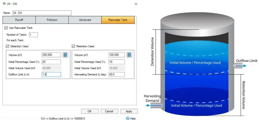
The ability to accurately model SuDS is only going to become more important in the future.
With InfoDrainage, you can model the effect of rainwater tanks on a sub-catchment level. This level of granularity empowers designers to specify crucial parameters, including the number of tanks, detention and retention volumes for stormwater control, outflow from the detention compartment, and the demand for rainwater harvesting from the retention compartment. With this powerful tool, designers can explore different demand values, allowing them to accurately size rainwater harvesting tanks based on specific requirements and test various options.
9. Validation *before* your analysis
In MicroDrainage, when encountering an error that prevented the model from being simulated, an error message would appear, indicating the specific location where the error occurred. Users would need to repeat this process iteratively, addressing each issue individually until all errors were resolved.
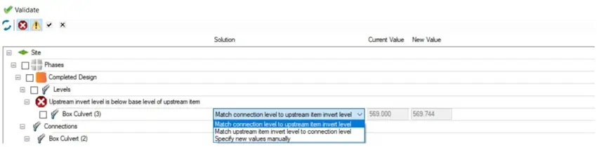
No more wasted time chasing down error messages. InfoDrainage has a validation tool.
InfoDrainage offers designers a valuable validation tool that identifies problematic errors and warnings, enabling users to address potential issues early on in a comprehensive list. In some cases, when issues are associated with levels, InfoDrainage provides designers with suggestions to implement for a fix in a simple click of a button.
10. Object and project templates
Unlike MicroDrainage, InfoDrainage introduces the convenience of Project and Object Templates. These templates serve as pre-defined starting points for designers and can be created to suit various needs such as specific clients, projects, or even countries.
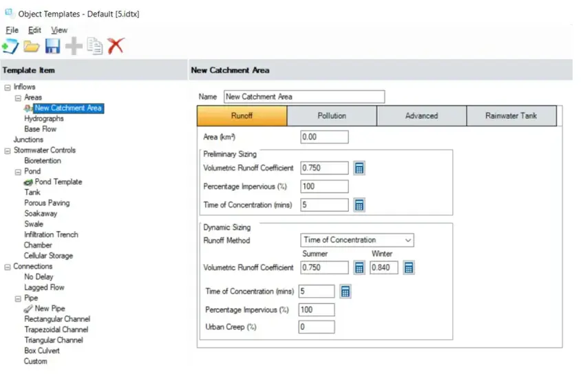
Templates in InfoDrainage can save you tons of time.
In simple terms, these templates significantly reduce the time spent by designers on repetitive data input when starting a new design. This streamlined approach enhances overall efficiency, allowing designers to focus more on the design process itself.
Take advantage of the InfoCare to Subscription (I2S) Programme to transition to InfoDrainage for more advanced tools, improved speed and accuracy, continuous feature updates, and enhanced integration with Civil 3D. Find out more here.
This article originally came from Autodesk. To read the full article, visit the Autodesk website HERE.