
Securing the Modern Workplace
Learn how to protect your organisation from QR code phishing, adopt passkeys securely, and manage AI note-takers with the latest IT security advice from Symetri.
It’s always a good idea to review the basics of what we do daily just in case we are missing a trick. It is all too easy to do the same thing day in, day out. In this blog I’m going to look at some basic structural elements and consider how custom Revit content could be created to save time and make detailing more consistent and robust.

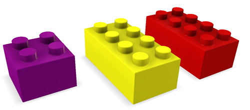
I often think of Revit as a digital Lego set. You have a certain number of pieces to assemble a structure, but the limitation is the variety of ‘bricks’ that are provided. For example, the three bricks below can only build simple, box like structures.
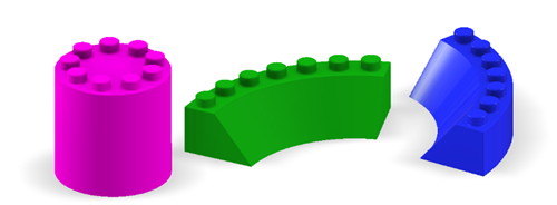
The great thing with Revit is that we can create our own parametric families that are either bespoke to a project or for use in many projects. The custom families give Revit the flexibility needed to create any type of family with fast and efficient placement into projects.
Let’s start with a simple example - the humble pile family.
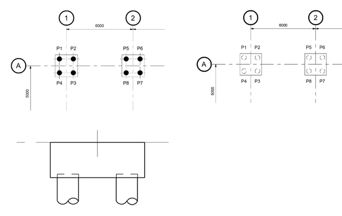
All too often, the default out of the box single pile, Pile-Steel Pipe.rfa is used for most projects. Whilst this is perfectly functional for most applications it may not deliver the best output and placement options. For example, the two images below show some typical ways of depicting piling in a plan view. The first image is perhaps appropriate when showing a piling layout, ideal for scales 1:100 where the pile may want to be displayed as a symbolic symbol. The second is useful for general arrangement plans and shows the pile in hidden detail under the pile cap. You can also see the pilling on the third image displaying the hidden detail for the embedment and the break symbol to curtail the full piling length.
The default pile family, when opened in the family editor, shows us the default Reference Planes which only run through the centre of the pile. This means that you cannot dimension the pile in elevation in a project. The default method of placement is to place the pile on a plane which is quite slow when multiple levels are required. This means you can’t snap a spot coordinate to the centre of the pile. This is simply down to the default family’s behaviour.
Once you place the piles, you will also need to detail these manually in a section or elevation with the break symbol. If the pile moves, you will also need to move the details.
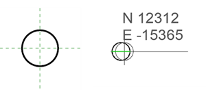
There are a few ways to improve your efficiency. One method is to create a face-based pile with all the relevant detailing built in. This means that if the pile cap, ground beam or foundation slab changed level, the piles will automatically move. The 2D details such as the symbolic view and pile break symbol are automatically added as the piles are modelled. You can also snap a spot coordinate onto the centre of the pile with confidence.
You can start by creating a new family using the Metric Generic Model face-based Revit family template. As there are a number of steps when creating the family, I have provided a short video with step by step instructions for the creation of the pile family.
You can make improvements to many of the default families which will save you time, increase your detailing efficiency and improve drawing consistency.
Have you considered Revit courses to improve your skills?
Start with our Revit Structure Fundamentals training course to learn the basics.
Then you're set to move onto more advanced Revit course, such as Revit Structure Content Creation.
For more information on our full range of Revit courses, visit our website here:
Alternately, give us a call to discuss your businesses requirements: 0345 370 1444
Learn how to protect your organisation from QR code phishing, adopt passkeys securely, and manage AI note-takers with the latest IT security advice from Symetri.

Reduce downtime and improve service efficiency with AI-powered troubleshooting. Learn how service teams use ilean to solve problems faster and capture knowledge.

Cybersecurity risks are not always caused by sophisticated attacks or major system failures. In many cases, risk builds quietly through everyday habits, overlooked processes, and limited visibility into where data is stored or how users interact with systems.