
How AI Is Transforming Daily Work in Service Teams
Reduce downtime and improve service efficiency with AI-powered troubleshooting. Learn how service teams use ilean to solve problems faster and capture knowledge.
In January 2020, Excitech was acquired by Addnode Group, the owner of Symetri, Europe’s leading provider of software and services for design and engineering activities.
Excitech has now become Symetri, operating as one company since the beginning of January 2021. Please rest assured it is business as usual for us and your service experience will not be impacted.
When you are modelling grading objects in Civil 3D, you may require using different slopes along the same feature line. While this is simple enough (just select ‘No’ when you get the ‘Apply to entire length?’ prompt in the command line), modelling the transition between those grading objects can require more care.

If the transition occurs along a straight line, you can use the ‘Create Transition’ tool, as shown below:
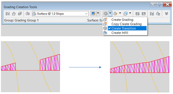
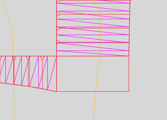
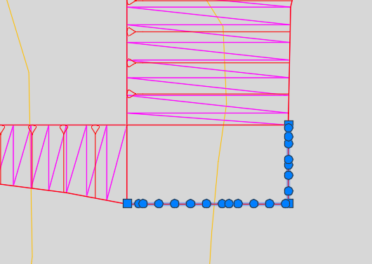
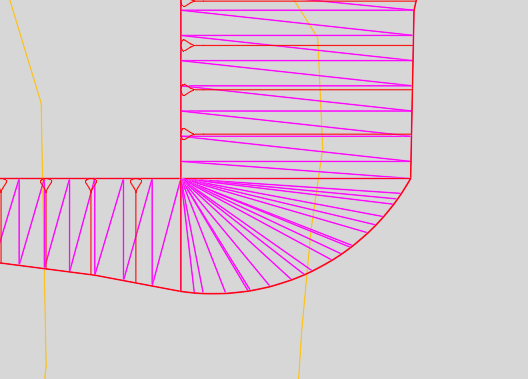
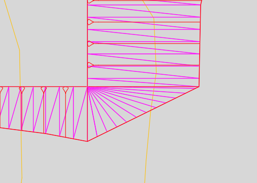
However, this tool in Civil 3D will not help if you want the transition to take place on a corner. In that particular case, the process is more manual. You will need to complete the top or toe of the slope with a feature line and then model the transition as an infill. The workflow is detailed below:
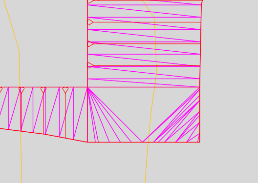
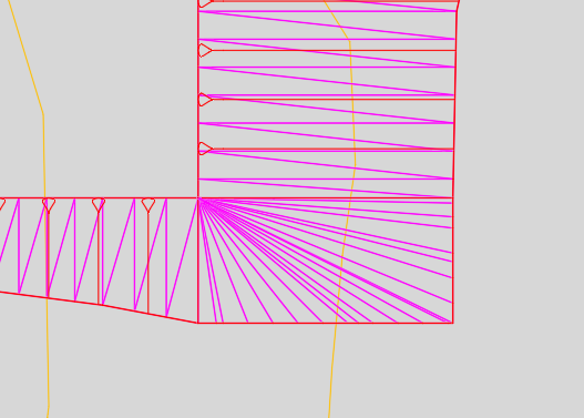
Depending on the constraints that you have, you may want to model the transition with a different geometry like an arc or a straight line.
I hope you found this useful. If you’re looking for further assistance with Autodesk Civil 3D to improve drafting, design, and construction documentation, we provide consultancy and training based on your specific needs.
We offer private and scheduled AutoCAD Civil 3D training courses, find out more here.
Reduce downtime and improve service efficiency with AI-powered troubleshooting. Learn how service teams use ilean to solve problems faster and capture knowledge.

Cybersecurity risks are not always caused by sophisticated attacks or major system failures. In many cases, risk builds quietly through everyday habits, overlooked processes, and limited visibility into where data is stored or how users interact with systems.

Learn how to reduce cyber risk through stronger security foundations. This month's bulletin covers home office security, legacy technology risks, vulnerability management, MFA, and cybersecurity best practices.