info@symetri.co.uk
Electro-mechanical Link - Linking Inventor Assemblies and AutoCAD Electrical Projects
In this blog article, we are going to look at the process of linking one project to another. Electro-mechanical links allow you to create a link between an AutoCAD Electrical project and an Inventor project.
Overview
An Electro-mechanical link allows you to create a link between an AutoCAD Electrical project and Inventor project. When you create a link between an AutoCAD Electrical and an Inventor project, the project files become associative: Electrical design changes made in one application are updated in the other through project synchronisation.

Process
The process of linking a project file from one application to the other involves two steps:
In either AutoCAD Electrical or Inventor, create the link file and point to the project for that specific application. In the other application, complete the link by browsing the previously created link file and pointing to a project in that application.
An example of the process is shown below:
- Create the Electromechanical Link file (AutoCAD Electrical or Inventor).


2. Select the Create option to create a new link file.

3. Specify the file name and shared location.

4. Once the link file has been created, the file will have to be linked in the other application. Note: This example shows the creation in AutoCAD Electrical and linking with Inventor


If you have link conflicts when synchronising between the AutoCAD Electrical project and Inventor, you can choose which application the information will be updated from.
5. The next step would be to map the 3D components within the AutoCAD Electrical catalogue database. This can be done in either application (the screenshot below is from AutoCAD Electrical).
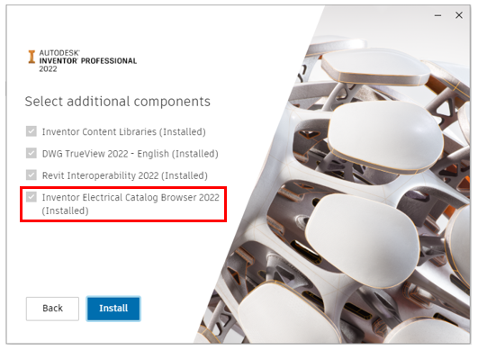
To insert the mapped 3D symbol within Inventor from the catalogue database, you must install the Electrical Catalogue Browser from the Inventor Installer (shown below). The Electrical Catalogue Browser for Inventor allows you to insert 3D parts by specifying a manufacturer number from the database. The utility includes the catalogue browser interface, the link to the AutoCAD Electrical database, and a sample set of 3D electrical components.
6. To define an Inventor component as an ‘Electrical Component’, the following must be assigned:
• Setup RefDes value to match the Component Tag value in AutoCAD Electrical
• Assign pin information related to the 2D symbol (TermXX) in AutoCAD Electrical
To associate wire information between AutoCAD Electrical and Inventor, the following must be assigned:
• Wire Type/Layer Name value to match the Wire Type value in the Cable and Harness Library
• Wire Numbers are to be populated in AutoCAD Electrical, and this information will populate the Wire ID value upon creating wire connections.
Note: All wires need connections on both ends!
7. To assign Inventor components as electrical components from AutoCAD Electrical, select the Location View. You can either assign existing Inventor components within an assembly to AutoCAD Electrical components or insert them from the catalogue browser, requiring the catalogue entry to have a 3D symbol mapped.


Insert From Catalogue Browser

Assign to Existing in Assembly

View the link status of a device as indicated by the icon next to the device tag:

8. To create the wire/cable connections within Cable and Harness, right-click on the assigned electrical component and select Create Connection. The wire numbers from AutoCAD Electrical will be populated to the Wire ID value within Inventor.
9. The wires/cables are routed with the functionality available within the Cable and Harness environment using segments.
If you would like further information on how to create links with Inventor and AutoCAD - Electrical, please get in touch with the Symetri team.
Contact us
By completing the form below or via email or telephone.
0345 370 1444
Bluebeam Max: The Superpower Taking Revu Into the AI Era
The construction industry is entering a new era, and Bluebeam is once again leading the way. In 2026, Bluebeam Max will launch as a new premium subscription that combines the power of Revu with advanced AI technology. This blog highlights just some of features you will expect to see within Bluebeam Max.
What’s New in Inventor 2027: A Guide to the Latest Features
Consultant Jason Kelly explores the new 2027 features in Autodesk Inventor Professional. Including updates to the content center and Autodesk Assistant
What’s New in Vault 2027: A Guide to the Latest Features
Vault 2027 release includes improved property handling, stronger PLM connectivity, and the introduction of the AI‑powered assistant.
+44345 370 1500 · info@symetri.co.uk