
How AI Is Transforming Daily Work in Service Teams
Reduce downtime and improve service efficiency with AI-powered troubleshooting. Learn how service teams use ilean to solve problems faster and capture knowledge.
In today’s complex market, engineers and designers constantly face new challenges within the manufacturing industry, including reducing costs and weight and faster developing innovative product designs.
Consequently, companies are now looking to incorporate some form of digital prototyping to help reduce design-to-market lead times.
Stress analysis is a key part of this digital prototyping process, enabling designers and engineers to analyse and validate designs before they are built. This also helps reduce the number of prototypes needed for physical testing before the first shipment.
Traditionally, stress analysis has been used by experts who spent most of their time on analysis and product validation before the first shipment. In recent years, software simulation and design companies like Autodesk have made stress analysis software easier to use and understand. This makes it easier for designers and engineers within the manufacturing industry to adopt analysis early on in the process; this is where stress analysis has the most impact. During a typical design process, designers and engineers go through a series of questions that are answered by building a working prototype or a series of prototypes. The primary issue with this method is that it is timely and costly. An alternative approach is to use stress analysis to validate designs before they are built. A typical stress analysis process involves four core steps:
Idealisation – simplify the geometry, including setting up the analysis.
Boundary conditions – apply constraints, including loads and material properties.
Run simulation and analyse – analyse initial results, including the convergence of results.
Optimisation – modify geometry to meet design goals, including changing original material.

This is the most important step and significantly impacts the speed and accuracy of the results. Assemblies and parts can be simplified and idealised within the modelling or stress analysis environment. Simplification within the stress analysis environment is typically restricted to excluding non-structural components and features. A common approach in idealisation is to reduce the model into half a model or even a quarter.
This step involves applying materials, constraints, loads and mesh elements. The material properties are carried forward from the environment of the part into the stress analysis environment. Typical constraints available include: fixed, pinned, and frictionless. For example, a fixed constraint is selected used if the component is fixed using bolts or welds. Various loads are available, including force, pressure, bearing load, etc. Stress analysis also allows the mesh size to be controlled globally and locally. Mesh size will have little effect on displacement results but can significantly impact stress results.
This step is primarily concerned with analysing the results and ensuring that the design is fit for purpose. One of the most important questions at this process stage is, ‘how do I know the stress results are correct?’ One way to answer this question is to ensure that the stress result converges. A solution is to run the simulation a minimum of three times in the area of interest, with the mesh size becoming finer in each simulation. If the stress value remains within a 10% difference between each simulation, then one can assume that the stress value has converged. It is normal to take the higher result from the last simulation for design verification purposes.
This final step of the stress analysis process helps to optimise designs. One example may be reducing mass against certain design criteria, such as maximum operating stress, overall displacement, etc. This is mentioned later in the ‘optimised designs’ section. Analysing and interpreting results is an important part of the stress analysis process. As mentioned earlier, it is essential to assess whether the stress result has converged. This process is referred to as manual convergence, and it can be established using the following methods:
Run analysis with default mesh settings. This will quickly check whether the structure is performing as expected.
Copy the simulation and re-run the analysis with a reduced mesh size with a value typically half the size of the default mesh size.
Copy the simulation and re-run the analysis with a finer global mesh. Alternatively, a local mesh control can be used around the area of interest.
To use local mesh control around an area of interest, it may be better to use split features to split the faces of the component.
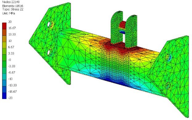
Normal and shear stress results can also help to better understand the behaviour of the structure by visually displaying tensile and compressive stress results, as illustrated in Figure 4.
A unique feature of CAD-embedded stress analysis software, such as Autodesk Inventor Stress Analysis, is the ability to perform parametric optimisation studies. Model parameters can be excessed within a stress analysis environment, providing the flexibility necessary to experiment with different design configurations.
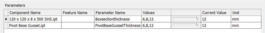
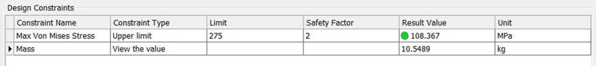
These configurations can also be validated against design constraints, including stress, mass, safety factor, etc., making it possible to create innovative designs.
More and more companies within the manufacturing industry today are taking further steps to help enhance design productivity using engineering simulation and analysis. To ensure best practices and return from the software, companies also use training and services provided by Symetri across the UK and Nordic countries.
However, no engineer would want to put speed above reliability in carrying out FEA testing tasks, especially in an area as safety-conscious as the manufacturing industry. Therefore, Symetri offers the design teams confidence with their simulation solution by working alongside our consultants either onsite or offsite on live projects.
For companies to remain competitive today and in the future, they need to empower designers and engineers with easy-to-use simulation tools to help them make better-informed decisions early on.
If you would like further information on Autodesk Inventor Stress or to discuss Autodesk Inventor Stress Analysis training, please fill in the form and contact the Symetri team.
Reduce downtime and improve service efficiency with AI-powered troubleshooting. Learn how service teams use ilean to solve problems faster and capture knowledge.

Cybersecurity risks are not always caused by sophisticated attacks or major system failures. In many cases, risk builds quietly through everyday habits, overlooked processes, and limited visibility into where data is stored or how users interact with systems.

Learn how to reduce cyber risk through stronger security foundations. This month's bulletin covers home office security, legacy technology risks, vulnerability management, MFA, and cybersecurity best practices.